2013 POTD Thread Archive

Today Im going to install a new shaft in the milling machine I made. The chuck broke off the last one and I have decided to go with an R8 shaft. Got the R8 Spindle shaft (LMS), the bearings, and 300 lbs of plate steel (found a new wreckers that has everything). Biggest problem Im going to have is getting the piece of 1" plate out of the van (its 180lb).
 
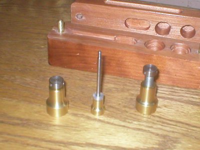
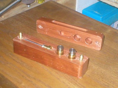
Made a set of screw jacks. Brass base with steel screw.
Drilled holes for leverage shaft and made a cedar holder for
them. Size closed is 1-1/4in Open is 1-3/4in. Don't know if
I will ever use them, but I had to make them.
Snugrat


P4020016.JPG P4020014.JPG
 
Still a cold 34F here this morning but did get in a little shop time.

First I ran errands for the wife and had coffee with a couple of the guys. Then I spent about an hour in the shop.

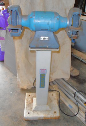
Sometime ago I got a Baldor grinder in a package deal. It was a bench mount model and I have no real bench in my shop, only a steel welding table. I have had a Craftsman 1/2HP grinder on a homemade stand for as long as I can remember so the Baldor had gone into storage. I recently ran across what was reportedly a Baldor grinder stand and I adopted it. This afternoon once the temperature came up a little I dug the Baldor out of storage and installed it on the new old stand. I left the rubber feet that were on it and used double nuts on the mounting bolts. I thought that the rubber feet might soften the vibration if needed. Stood to one side and turned it on and it is so smoooooth!

The Baldor seems to be much more a heavy duty grinder than the Craftsman.

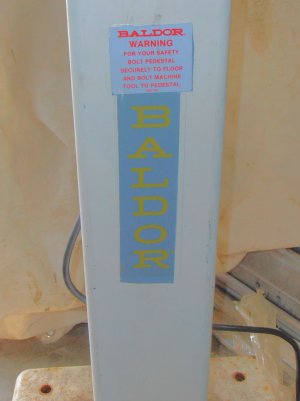
First photo shows the grinder bolted on the stand. The grinder was painted a blue color at some point in its life, ID tag and all. The second photo shows what I assume is the original Baldor labels on the stand. The stand had been repainted a kind of off-white color but at least someone made and effort (a poor one) to mask off the labels. The stand has nice heavy cast base and top with what appears to be steel upright.
Baldor Grinder&Stand.jpg Baldor Label.jpg
Can’t wait for warm weather!

Benny
The Orphanage Never Closes

Baldor Grinder&Stand.jpg Baldor Label.jpg
 
Very cool! I lost track of how many times some jacks like that would have saved my bacon. I gotta make some one of these days.

Ray

Made a set of screw jacks. Brass base with steel screw.
Drilled holes for leverage shaft and made a cedar holder for
them. Size closed is 1-1/4in Open is 1-3/4in. Don't know if
I will ever use them, but I had to make them.
Snugrat
 
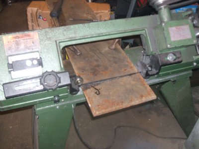
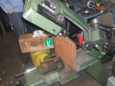
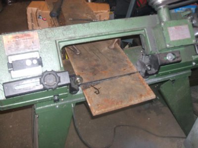
I finally got a day to start working on building my spindle box for my Home Made Milling Machine. Had to do some fine and delicate work making my 4 1/2" band-saw cut 9" and 12" plates. Seems without the guide and vise, I can cut 9" horizontally (I love C Clamps)

DSCF6775.JPG

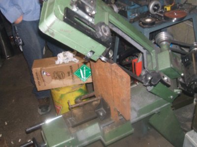
and 12" vertically.

DSCF6776.JPG

DSCF6775_zps5265945a.jpg DSCF6776_zps7c11157e.jpg DSCF6775.JPG DSCF6776.JPG
 
Last edited:
Just found this thread, very cool, I will post when I can, been very busy. Yesterday I went and took apart a burk #4 mill that I purchased on saturday, loaded it into my truck with the help of a friend, waiting till the weekend to get it in my basement shop and reassembled.
 
Stern, your project of making a mill intrigues me greatly. I am in the" research" stage of making a lathe. Your Spindle Box design could be adapted as a headstock. I've also been tossing around the idea of a horizontal mill, with lathe capability?:nuts: Do you have any drawings or photos? I would love to see them. I'm not as computer savy as most, but I've heard of others finding out how to post pictures and such elsewhere on this GREAT site. I'd help, but I'm writing this with my "typing finger". Please keep trying. Thanks, and good luck with the mill.
 
Stern, your project of making a mill intrigues me greatly. I am in the" research" stage of making a lathe. Your Spindle Box design could be adapted as a headstock. I've also been tossing around the idea of a horizontal mill, with lathe capability?:nuts: Do you have any drawings or photos? I would love to see them. I'm not as computer savy as most, but I've heard of others finding out how to post pictures and such elsewhere on this GREAT site. I'd help, but I'm writing this with my "typing finger". Please keep trying. Thanks, and good luck with the mill.

If I had any drawings I would sure share them, but I must admit (cringes) Im kind of a "wing it" guy lol. Since I not a machinist (hobby really, my main field was electronics) I just get in there and start doing it, and usually changing it several times to fix my errors lol. I used to do a lot of schematic and PCB work, and even a bit of CAD .... and what I have learned is if I make drawings, I never even get to start the job lol.

I have a blog of the construction of it (started with a steel frame with a X-Y T-slot table, and a Z column that moves a large dovetail block), which was once a surface grinder project until the 2 stock bench grinders I used both died lol. This spring it was "find a use for the stand or cut it up for scrap, so I decided to make a mill. It worked well until the chuck broke off (shaft wasn't hardened) so I decided to change it for an R8 Spindle (LMS). Its not precision work, but should be a beast when I get it fixed.

http://homemademillingmachine.blogspot.ca/

Also decided i wanted an index head/table, so used a 30:1 gear-head from the mark one mill failure to start building it. Going well, but need the mill to work to finish it.

http://homemadeindexinghead.blogspot.ca/
 
So this thread has motivated me to do something and get off my backside. So I went downstairs to the shop and sorted through the bucket of stuff that I got as a freebie when I purchased the mill, I found a couple more boring bars and about a half dozen or so clamp t nuts that I think are for the mill. Then I looked at the vertical milling attachment to check it out and it looks like it is in great shape, definitely 3C as I have a set of collets for it and the collet nut/drawbar. Found a few more bits of hss stock in the bucket too. It looks like everything is there for the table feed, even both halfs of the drive shaft and universals. I think the po removed it and mounted an electric power feed to it. Then I finished up a little wiring in the shop by the lathe and installed 3 outlets. Then I moved the lathe to it's final resting place near the wall. Pretty productive evening after working 2 jobs.
 
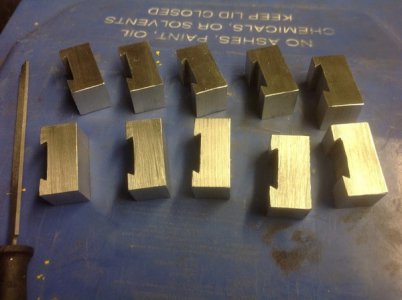
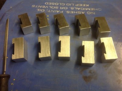
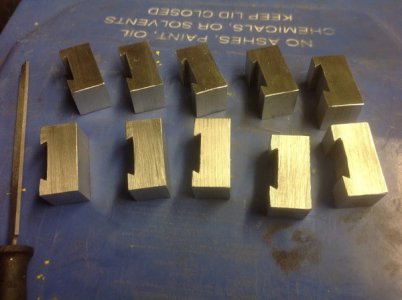
Well, I cut up some extra tool holders for my QCTP. It's not quick change if you have to swap tools out of them. Yes, they are aluminum. My little 350W motor can't push that hard. I already had the dovetail cut in the stock for a TP I was making before I got my bargain 0XA and just widened it for this one. Now I just have to mill the tool slot and drill and tap all the holes. Not sure if I have enough set screws for them yet. The fun part will be making the adjuster screws. I brought home a hand full of my favorite alloy: Free steel. They are 1/2" dia. test pieces that they use in materials classes to test breaking strength.

13+-+1.jpg

13+-+1.jpg

13+-+1.jpg
 
Back
Top