2013 POTD Thread Archive

Brain,

Nice job on the repair you did!

That ought to last another four generations of use.
 
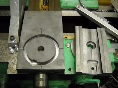
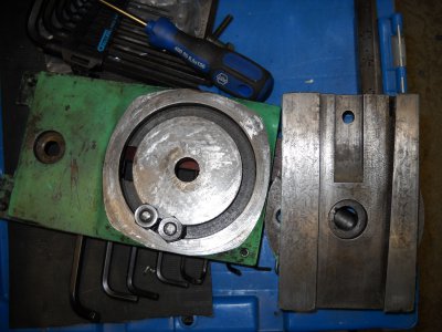
Here's what I've been working on this past month between the hours of 10:00pm and 6:00am.

I making a new cross slide and compound slide for my 13" Sheldon Sebastian lathe.

There's more to come. Will start a new post.

DSCN1702.JPG DSCN1703.JPG
 
Hello Ken,

Thanks a bunch... !!! I had never used a lathe until I bought this one and the repair was intimidating at the start, but by the end of it, I had learned quite a bit from others to think outside the box. I also learned, that with the right set-up and measuring process, you can still turn out an extremely accurate part from a worn out machine. This lathe came out of a local blacksmith's shop and was owned by a retired employee of that shop until he had to be placed in a home at the ripe old age of 88. It was my pleasure to strip this lathe down and restore it to a workable condition.

I am glad to be a new member here and am looking forward to learning from all of you.

Cheers...

Brian

- - - Updated - - -

Here's what I've been working on this past month between the hours of 10:00pm and 6:00am.

I making a new cross slide and compound slide for my 13" Sheldon Sebastian lathe.

There's more to come. Will start a new post.

Wow... !!! That's quite a project you've taken on. Just a wee bit over my head, but I am looking forward to seeing how you do this. Lots of pics and explanations I hope....

Brian
 
Brain,

I was quite impressed with the condition that old lathe is in. Not bad for a 100 year old lathe. Hope it gives you many more years of use, and with a little maintenance like making new gears for the gear train will definitely add life to her!

My lathe was in rough shape when I bought it over 35 years ago. I reconditioned it at that time, re-scraped the slides and such, had to replace the rack pinion gear very similar to what you did. That fix is still doing good all these years. There's several events leading up to the major repairs I'm doing now. I'm going to save it for my story later.

Oh, before I forget, as I always do. Welcome to the forum.
 
Hi Ken, thanks for the welcome to the forum .... :)

This lathe was in fairly rough shape when I bought it, but had very little rust to speak of, so I tore it down to the last nut and bolt and cleaned and repaired as I went. The ways are worn, as one might expect, but with a little care, you can still turn out some very decent parts. I really love to learn and am thoroughly enjoying the exciting adventure of learning machining that I have chosen.

It's a pleasure to meet you Ken and am looking forward to seeing your posts.

Cheers...

Brian
 
Hello all,

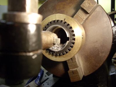
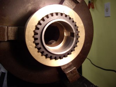
Spindle gear being bored then keyed on the lathe with the carriage...

IMGP1921800x600.jpg

IMGP1928800x600.jpg

Brian

Hello Brian

Being that I am a newbie and don't know much of anything about lathes etc. It intrigues me how you performed the task of cutting the inside keyway in the gear on the lathe.

Would you be so kind as to describe how you went about to "key" that spindle gear on your lathe?

I know there are others like me reading this now or that may read it in the future that would greatly benefit from your knowledge.

Thanks for the interesting post.
 
Last edited:
Hello Goat Driver,

First of all , I need a real name.... like Bob or Ken to call you. :))

Using the same boring bar that I had bored the gear with, I ground a 7 degree relief angle on a peice of HSS tool bit that had the same dimension as the key that I wanted to cut. In this case it was 1/4" . I simply ground a 7 degree end clearance angle, hand honed it with a small stone and oil, and mounted the tool bit in the boring bar holder with the square top edge facing the chuck and the 7 degree relief angle pointing back towards the tailstock. By eye, I rotated the boring bar until it looked like the tool bit was roughly horizontal.

This keying procedure is done without power to the lathe of any kind but muscle power. I engaged the back gears of the lathe to eliminate the spindle turning on me while keying. I also drove a wooden wedge between the cone pulley and the housing. Then I advanced the carriage towards the chuck until the tool bit was close to the bore opening and used the cross-slide to adjust until the tool bit was in close contact with the bore.

Whether the tool bit is exactly horizontal or vertical or anywhere in between is not important. What matters is that both edges of the tool bit are in contact with the bore at the same time. I rotated the boring bar and manipulated the cross- slide and carriage until both points of the flat were in contact. I then advanced the cross-slide .001" and used the carriage handwheel to push the cutter into the bore. I visually verified that it was cutting equally on both corners and made sure that the boring bar was snug and continued to feed 001" at a time and running the tool in and out.

You need to be patient and not be tempted to increase the cut to hurry it along. Just relax and get into a rhythm..... it took about 5 minutes to cut this keyway. I don't have keyway broaches as of yet and this was a method that was passed along to me that served the purpose and the end result was very good.

I hope that I haven't been too long in the tooth in my explanation and that I have answered your question. Don't hesitate to ask more questions of me. I am fairly new to machining and am here to learn...

Cheers...

Brian
 
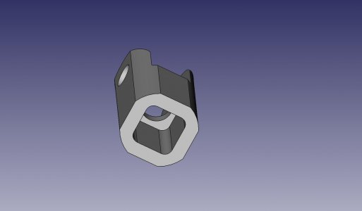
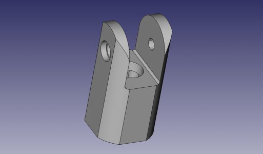
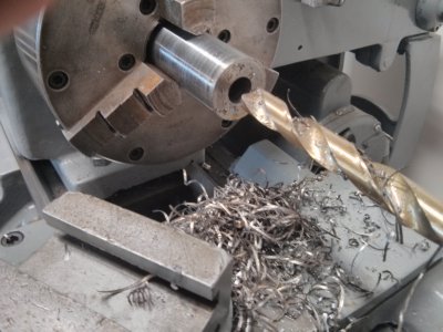
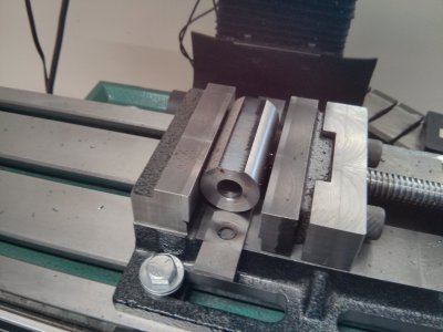
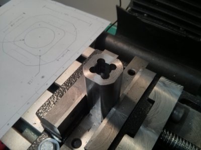
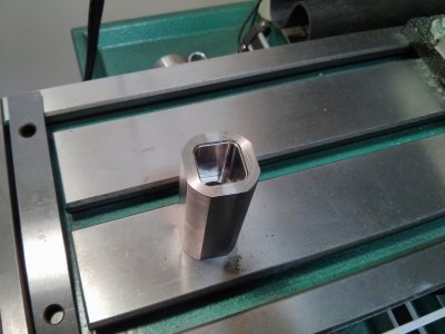
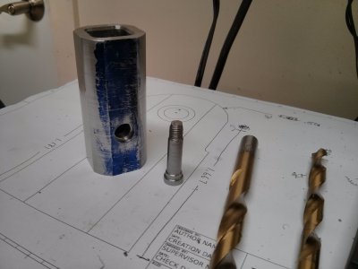
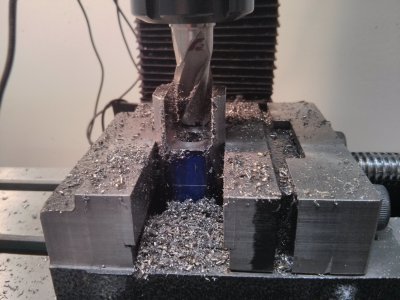
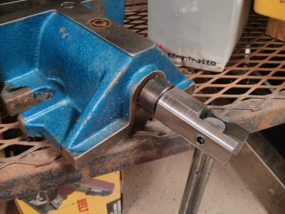
For my first reasonably complex shop project, I decided to make a handle for a Bison 2 piece milling vise I bought on eBay. It has a 17mm square drive and the only handles I could find with a matching socket are one piece and look like cast iron (though they may be forged steel). I wanted a Kurt-style swiveling handle. I started with a piece of 1.25" 4140 and trued and faced it, then used freeCAD to model the handle based around the dimensions of my stock. I still need to round off the ears, but I need to move my X axis DRO to accommodate my rotary table's handle and get some work holding gear figured out for it first.

Obviously the real goal with this one was to make a vise handle, not simply to have a vise handle :)

vise handle.jpg
vise handle 2.jpg
2013-08-30 13.38.40.jpg
2013-08-30 15.13.23.jpg
2013-08-30 18.01.56.jpg
2013-08-30 23.04.51.jpg
2013-08-31 18.25.34.jpg
2013-08-31 19.57.11.jpg
2013-08-31 21.03.30.jpg

vise handle.jpg vise handle 2.jpg 2013-08-30 13.38.40.jpg 2013-08-30 15.13.23.jpg 2013-08-30 18.01.56.jpg 2013-08-30 23.04.51.jpg 2013-08-31 18.25.34.jpg 2013-08-31 21.03.30.jpg 2013-08-31 19.57.11.jpg
 
For my first reasonably complex shop project, I decided to make a handle for a Bison 2 piece milling vise I bought on eBay. It has a 17mm square drive and the only handles I could find with a matching socket are one piece and look like cast iron (though they may be forged steel). I wanted a Kurt-style swiveling handle. I started with a piece of 1.25 4140 and trued and faced it, then used freeCAD to model the handle based around the dimensions of my stock. I still need to round off the ears. I need to move my X axis DRO to accommodate my rotary table's handle and get some work holding gear figured out for it first.

Obviously the real goal with this one was to make a vise handle, not simply to have a vise handle :)
QUOTE]


Very nicely thought out and accomplished !!! Your handle has given me some ideas about a microscope stand that I am planning on machining.

Brian
 
Hello Goat Driver,

First of all , I need a real name.... like Bob or Ken to call you. :))

Using the same boring bar that I had bored the gear with, I ground a 7 degree relief angle on a peice of HSS tool bit that had the same dimension as the key that I wanted to cut. In this case it was 1/4" . I simply ground a 7 degree end clearance angle, hand honed it with a small stone and oil, and mounted the tool bit in the boring bar holder with the square top edge facing the chuck and the 7 degree relief angle pointing back towards the tailstock. By eye, I rotated the boring bar until it looked like the tool bit was roughly horizontal.

This keying procedure is done without power to the lathe of any kind but muscle power. I engaged the back gears of the lathe to eliminate the spindle turning on me while keying. I also drove a wooden wedge between the cone pulley and the housing. Then I advanced the carriage towards the chuck until the tool bit was close to the bore opening and used the cross-slide to adjust until the tool bit was in close contact with the bore.

Whether the tool bit is exactly horizontal or vertical or anywhere in between is not important. What matters is that both edges of the tool bit are in contact with the bore at the same time. I rotated the boring bar and manipulated the cross- slide and carriage until both points of the flat were in contact. I then advanced the cross-slide .001" and used the carriage handwheel to push the cutter into the bore. I visually verified that it was cutting equally on both corners and made sure that the boring bar was snug and continued to feed 001" at a time and running the tool in and out.

You need to be patient and not be tempted to increase the cut to hurry it along. Just relax and get into a rhythm..... it took about 5 minutes to cut this keyway. I don't have keyway broaches as of yet and this was a method that was passed along to me that served the purpose and the end result was very good.

I hope that I haven't been too long in the tooth in my explanation and that I have answered your question. Don't hesitate to ask more questions of me. I am fairly new to machining and am here to learn...

Cheers...

Brian


Thank you Brian for that well versed explanation of the process. I had in mind before I asked that that would be the most likely way to go about doing the keyway. At least I know that my mind is on the same page as you guys. :thinking:

Thanks again,
M.L.
 
Back
Top