2016 POTD Thread Archive

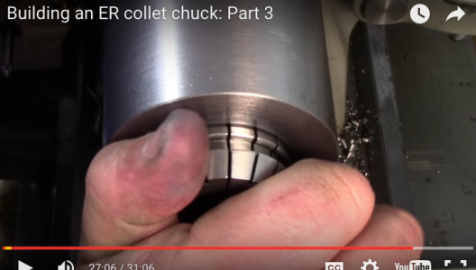
That looks an interesting exercise Matt.
Do you have any idea as to the accuracy of the hexag set up being held in the chuck , against me using a morse taper with my collets in the spindle tube which is perhaps four inches shorter from the spindle thread's register face ?
how do you mean David? with the collet chuck threaded onto the spindle or held in another chuck? threaded onto the spindle it should be as accurate as my spindle + any inaccuracies in the taper + any inaccuracies in the collets. probably a bit more than collets held in the spindle, everything else being equal, but has some other advantages - notably size range, spindle pass through and cost. this cost me $22 after a partial refund for the collets and a garage sale find for the wrench.
 
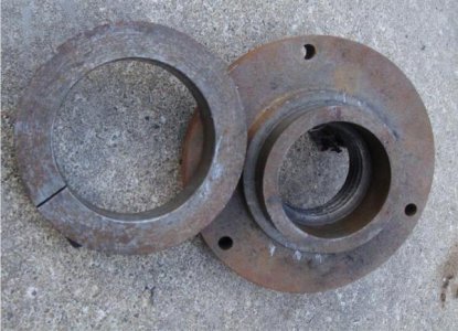
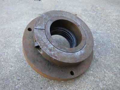
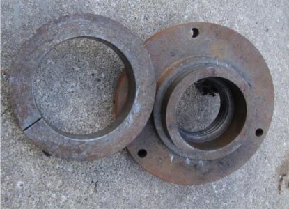
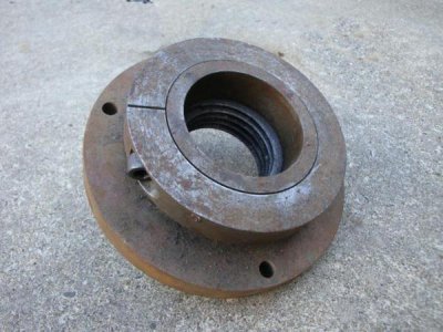
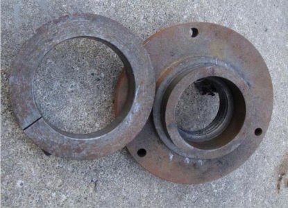
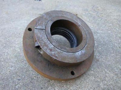
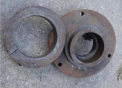
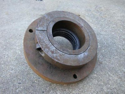
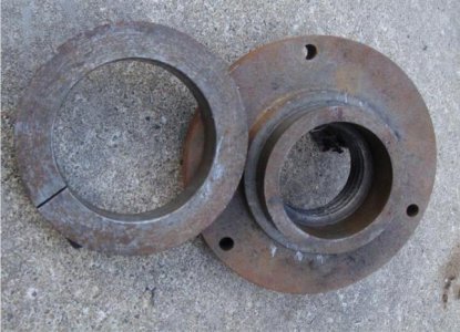
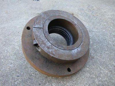
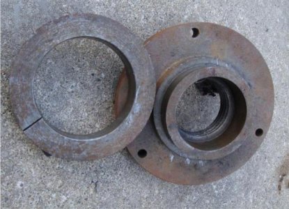
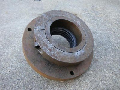
I'll be making a "schaublin" style collar for use with my next backing plate on my Atlas to keep the chuck from turning off in reverse.

Looks like this:

15209d1252158700-anchoring-chuck-threaded-spindle-flens1.jpg

15210d1252158747-anchoring-chuck-threaded-spindle-flens-003.jpg

My issue is going to be cutting the threads. I haven't cut any threads at all on the lathe as of yet.

Gonna have to figure it out though. I need to cut metric threads and from what I understand, I'll need to run the lathe in reverse in order not to mess up metric threads....


Hey,

I dont understand it.

How does that collar prevent the chuck from unscrewing please ?

Bill

15209d1252158700-anchoring-chuck-threaded-spindle-flens1.jpg

15210d1252158747-anchoring-chuck-threaded-spindle-flens-003.jpg

15209d1252158700-anchoring-chuck-threaded-spindle-flens1.jpg

15210d1252158747-anchoring-chuck-threaded-spindle-flens-003.jpg

15209d1252158700-anchoring-chuck-threaded-spindle-flens1.jpg

15210d1252158747-anchoring-chuck-threaded-spindle-flens-003.jpg

15209d1252158700-anchoring-chuck-threaded-spindle-flens1.jpg

15210d1252158747-anchoring-chuck-threaded-spindle-flens-003.jpg

15209d1252158700-anchoring-chuck-threaded-spindle-flens1.jpg

15210d1252158747-anchoring-chuck-threaded-spindle-flens-003.jpg
 
I've been working on my CNC conversion of X and Y on my G0704. I made up the motor mounts as my first real milling project. Lesson learned here was read the prints carefully. One of the cap screw holes for mounting to the mill was off .06", so I had to make it into more of a slot than a hole.

DSCN0356_zpsdzqgf6le.jpg

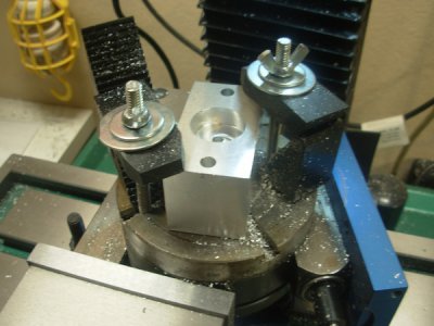
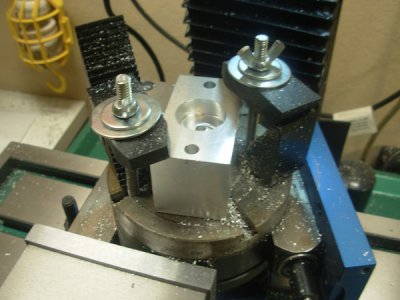
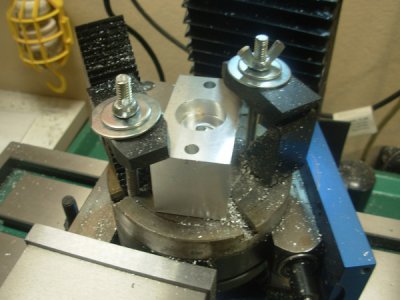
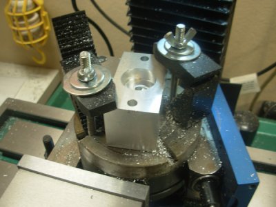
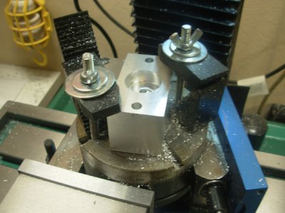
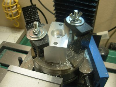
Then I got to the Y spacer that houses the bearings. I don't have a boring head, nor do I have a 4 jaw chuck for my lathe, but the bearing recesses need to be pretty accurate. As I thought about it, I remembered I have a really small rotary table that is actually a Sherline 4th axis. The slots will just fit a 1/4" bolt, so I ground 2 down to make stud/T-nut combos and was able to just barely get everything on there. I took my time centering the table to the spindle and then the work piece to the spindle. One side came out a few thousandths over tolerance (oops), but the other side was bang on. I think I can still use it fine. This was a fun piece, but some of the setup felt kind of Rube-Goldberg-y.

DSCN0355_zpsvtyxa1yw.jpg

DSCN0356_zpsdzqgf6le.jpg

DSCN0355_zpsvtyxa1yw.jpg

DSCN0356_zpsdzqgf6le.jpg

DSCN0355_zpsvtyxa1yw.jpg

DSCN0356_zpsdzqgf6le.jpg

DSCN0355_zpsvtyxa1yw.jpg

DSCN0356_zpsdzqgf6le.jpg

DSCN0355_zpsvtyxa1yw.jpg

DSCN0356_zpsdzqgf6le.jpg

DSCN0355_zpsvtyxa1yw.jpg
 
Ham radio? Is that still around? I gave up on it about 20 years ago.
Matt, Ham radio is still around and very much alive. With the code requirement gone, we are seeing more and more folks getting their licenses.
It is a great hobby and incase of a major disaster, it may be the only communications available.
Cell towers may be down.
 
Matt, Ham radio is still around and very much alive. With the code requirement gone, we are seeing more and more folks getting their licenses.
It is a great hobby and incase of a major disaster, it may be the only communications available.
Cell towers may be down.
I find "very much alive" to be kind of area dependent.

Depending on location/channel, I find everything from dead silence to old farts who don't like you on "their freq".

Cb isn't much better these days either. Silence, total a-hole potty mouths, gibberish lingo or guys unzipping their fly's trying to outpower one another.


I find radio has generally gone to H ee double hockey sticks everywhere except the official freqs (I'm in aviation) or ones that are owned by someone for industry.

Doesn't really matter I guess. All the interesting stuff happens on trunked/coded systems anyways now...
 
Last edited by a moderator:
Forgot to take a picture but I milled a slot into a 2.375 round, on the face, 3/4 wide 1-1/4 deep, the metal was a cutoff of some big threads, soft as all get out, the guy is going to use it to push down on the press break die I made for him, I did it with a 3/4 em taking .100 passes and then cleaned up the walls climb cutting with a nice fit to the die
 
I powered the head on my PM25 mill today. Not for machining purposes, but for saving the rotator cuff on my right shoulder.
I've been working toward this for a couple of weeks, I started with a junk yard windshield wiper motor from a Ford Windstar,

The project began with mounting a ball bearing on the shaft for the head crank. I was able to replace the crank after the bearing was in place. I was amazed at how much easier the head moved up and down.
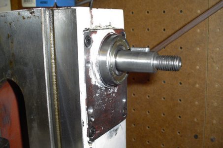
1 Carrier and Bearing.jpg


I learned quite a bit about the construction of this portion of the machine in this process. The lead screw, inside the column has a thrust bearing on top, easing considerable friction there. I mounted a piece of 3/8 by 4 aluminum on this carrier, adding support to the bearing and supporting the motor.
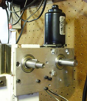
2 Mounting plate and motor sm.jpg

The cluster of cap screws in the center bottom supports a block bearing against the body to support the weight of the motor. There are four screws mounting the plate to the column and three cap screws mounting the motor to the plate. There appear 6 extra mounting holes where I tried to locate the motor in earlier attempts. Not errors, just developments.

From the back the motor looks like this.
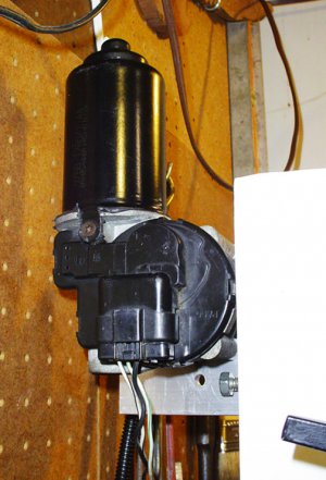
3 Head motor, rear sm.jpg

Here's the head and the control. I take little pride in my sheet metal work. The red off/on switch is a dummy, the green push button is normally off, the two toggles are (on the left) high and low speed, and on the right, up and down. I elected not to put in a variable speed control.
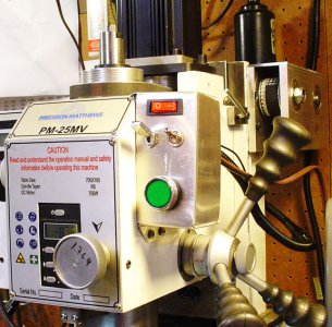
4 Powered head sm.jpg

And the drive unit all bolted together and ready for service.
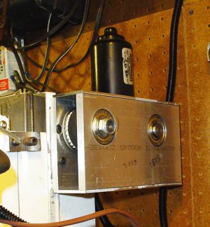
5 Drive buttoned up sm.jpg

I'm looking forward to a lot of use, saving my shoulder. It's a bit slower than I can crank, but a lot easier.
 
as you are testing do you think you should have a rod snug in the collet to keep it from bending

Screen Shot 2016-01-08 at 3.34.41 PM.png
 
Back
Top