- Joined
- Feb 8, 2014
- Messages
- 11,176
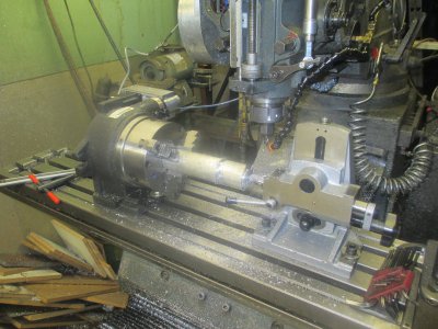
A few months ago I picked up an unused 6 inch Vertex Super Spacer almost free. Cost me about $80 in materials and a couple hours labor. 
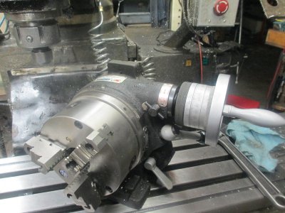
But this is about powering it up.
The job that I got it for finally is ready to go so now I need the 4th axis on my machine. The goal here is to install the stepper drive without modifying the original hardware. What I came up with is clamping the assembly onto the cam support shaft. That way I can just remove it and am back to normal operation.
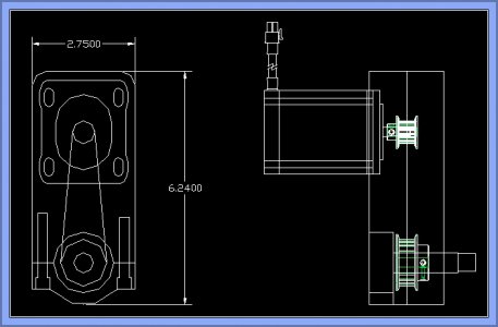
The concept drawing
So first operation is to square up the 1x4 aluminum. Then drill the cap screw holes in the housing. This is so can bolt the cap in place later without disturbing the setup when ready for that operation. These are just drilled for tap size, but will be tapped later.
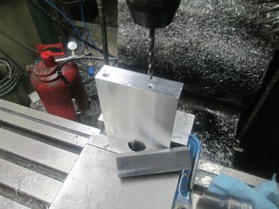
Then drill the cap and counter bore to depth for the cap screws. The depth of the counter bores are set so that in subsequent operations, the end mill will not hit the cap screws.
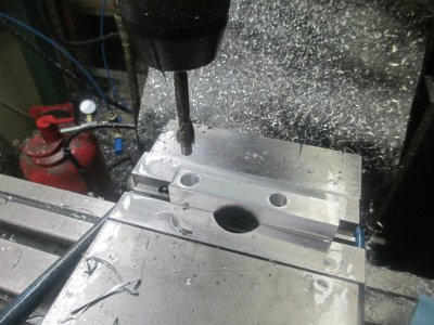
The first operation was to cut the pocket for the cap, once that was done, then the holes were tapped and the cap bolted into place. Then the various pocketing operation were done on the entire motor side.
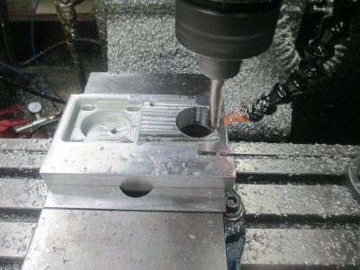
And the completed motor side operations
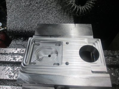
And the pocketing is complete on the belt side.
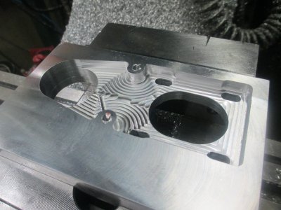
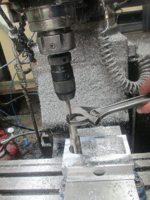
The pocketing is complete on the belt cover. Tapping the 1 inch -32 hole for the shaft cover. Why did I use a 1-32? Because I had a tap for that, it’s a standard C-mount lens size. Here I’m using a 3/8 tap as the center point to keep the tap on center. Keep down pressure on the quill while turning the tap. (the quill is vertical, I was just holding the camera at an angle)
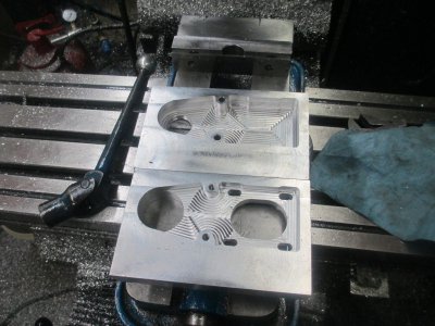
And the almost completed pieces. Now the outside profile needs to be done.
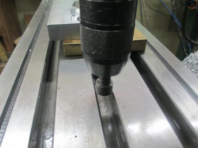
Setting the zero to the center of the T-slot, I just use a ½ inch cap screw in the chuck to get pretty close. Does not need to be dead on.
First anchor one side of the motor mount down to the table with a chunk of MDF board under.
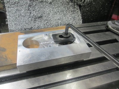
Now indicate the side to align it to the table. I used the Blake because it will be used in the next operation.
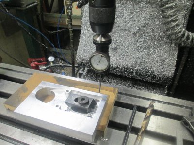
Next is locate the clamp hole. All of the features are relative to this location. This is located at -6.115,-2.000
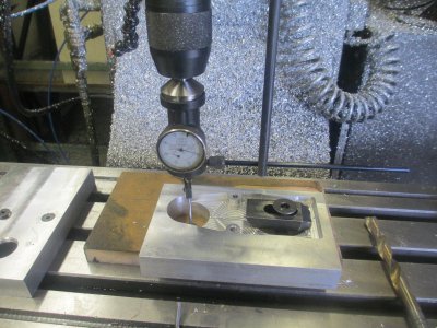
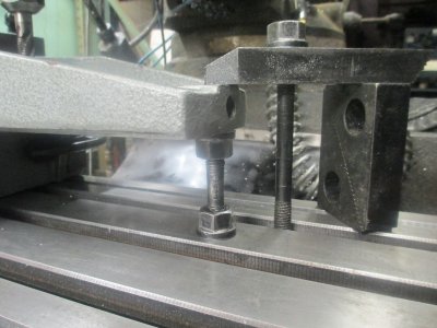
Now bolt down the belt cover. I am using a feeler gauge under the bolt to make sure it does not bottom in the T-slot.
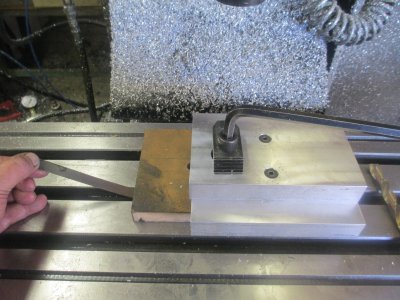
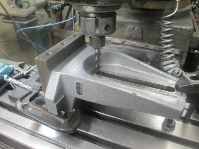
I had to change to washers under the bolt rather than the clamp. The collet nose would have hit the clamp. There is a thread on H-M about using a mill as a band saw, well that’s kinda what I am doing here. I could have trimmed these on the band saw, but I got lazy, just press go and come back when it’s done.
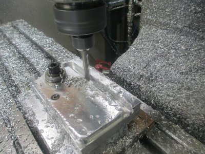
Getting close
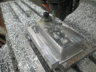
Corner rounding the edge with a Harbor Freight carbide router bit.
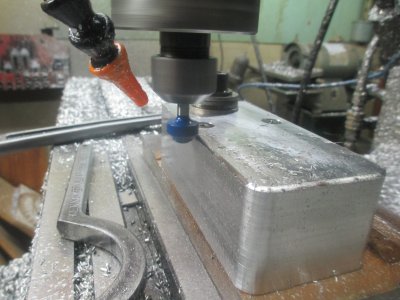
The motor mount ready to ready to install
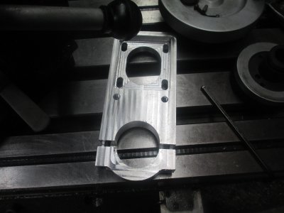
And the motor is mounted
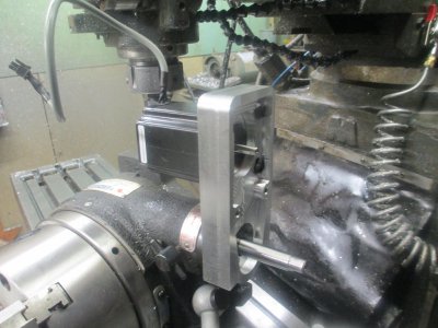
The trained monkeys pulled the wrong pulley for the 3/8 wide belt order, so I just pulled the front flange off. The belt won’t come off, the bottom flange will hold it.
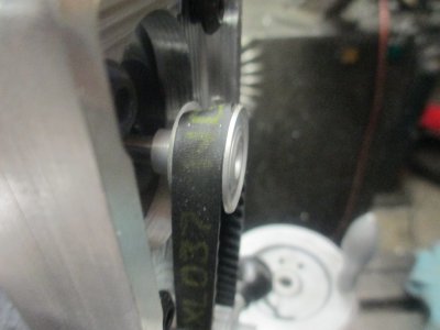
And the belt and pulleys installed.
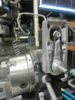
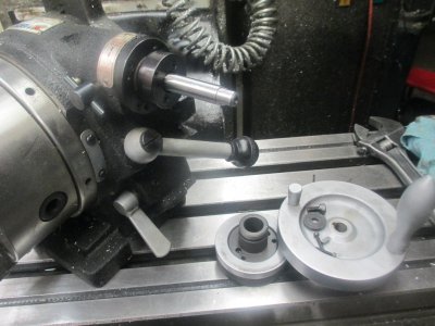
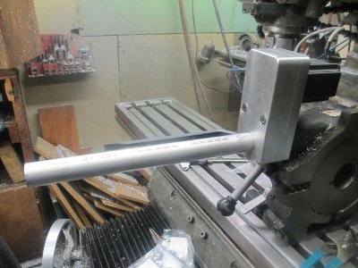
Has a bit of a snout sticking out, need to cover that. A handle can be installed for hand operation with the motor installed.
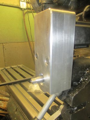
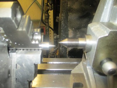
I made the shaft cover from 1.125 aluminum bar stock. Since the thread length is only 3/8 inch and it’s to a shoulder, I turned the tool up side down and ran the lathe backwards. I did the threading at 460 RPM. Made nice threads.
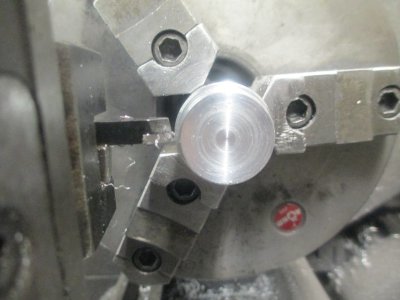
Fits nice but maybe it’s a bit long. We can call it Pinocchio
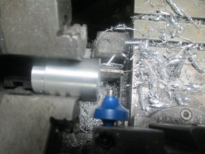
Corner rounding on the lathe, another HF carbide router bit. Work back & forth between the edges, don’t try to take a full width cut, it’s not stable enough.
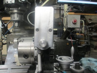
The face wasn’t planned, but its kind of cute.
The assembly can be used both horizontally as well as vertical just by loosening the cap screws and rotating around.
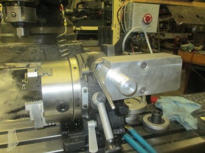
Next is to install the drive and then write the software. That may get done tomorrow. I'll post pictures of it actually being used pretty quick.
.
.

But this is about powering it up.
The job that I got it for finally is ready to go so now I need the 4th axis on my machine. The goal here is to install the stepper drive without modifying the original hardware. What I came up with is clamping the assembly onto the cam support shaft. That way I can just remove it and am back to normal operation.

The concept drawing

So first operation is to square up the 1x4 aluminum. Then drill the cap screw holes in the housing. This is so can bolt the cap in place later without disturbing the setup when ready for that operation. These are just drilled for tap size, but will be tapped later.

Then drill the cap and counter bore to depth for the cap screws. The depth of the counter bores are set so that in subsequent operations, the end mill will not hit the cap screws.

The first operation was to cut the pocket for the cap, once that was done, then the holes were tapped and the cap bolted into place. Then the various pocketing operation were done on the entire motor side.

And the completed motor side operations

And the pocketing is complete on the belt side.

The pocketing is complete on the belt cover. Tapping the 1 inch -32 hole for the shaft cover. Why did I use a 1-32? Because I had a tap for that, it’s a standard C-mount lens size. Here I’m using a 3/8 tap as the center point to keep the tap on center. Keep down pressure on the quill while turning the tap. (the quill is vertical, I was just holding the camera at an angle)

And the almost completed pieces. Now the outside profile needs to be done.

Setting the zero to the center of the T-slot, I just use a ½ inch cap screw in the chuck to get pretty close. Does not need to be dead on.

First anchor one side of the motor mount down to the table with a chunk of MDF board under.

Now indicate the side to align it to the table. I used the Blake because it will be used in the next operation.

Next is locate the clamp hole. All of the features are relative to this location. This is located at -6.115,-2.000

Now bolt down the belt cover. I am using a feeler gauge under the bolt to make sure it does not bottom in the T-slot.

I had to change to washers under the bolt rather than the clamp. The collet nose would have hit the clamp. There is a thread on H-M about using a mill as a band saw, well that’s kinda what I am doing here. I could have trimmed these on the band saw, but I got lazy, just press go and come back when it’s done.

Getting close

Corner rounding the edge with a Harbor Freight carbide router bit.

The motor mount ready to ready to install

And the motor is mounted

The trained monkeys pulled the wrong pulley for the 3/8 wide belt order, so I just pulled the front flange off.

And the belt and pulleys installed.

Has a bit of a snout sticking out, need to cover that. A handle can be installed for hand operation with the motor installed.

I made the shaft cover from 1.125 aluminum bar stock. Since the thread length is only 3/8 inch and it’s to a shoulder, I turned the tool up side down and ran the lathe backwards. I did the threading at 460 RPM. Made nice threads.

Fits nice but maybe it’s a bit long. We can call it Pinocchio


Corner rounding on the lathe, another HF carbide router bit. Work back & forth between the edges, don’t try to take a full width cut, it’s not stable enough.

The face wasn’t planned, but its kind of cute.


The assembly can be used both horizontally as well as vertical just by loosening the cap screws and rotating around.

Next is to install the drive and then write the software. That may get done tomorrow. I'll post pictures of it actually being used pretty quick.
.
.
Last edited:

 No problem, I figured out a quick work around.!