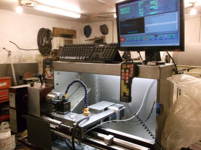
9x20 Lathe CNC conversion

hi Mark
You have me a bit confused?
quote " When ever you get a free second can you take some close up pictures of the mill with the ball screws. "
are you wanting to see the pics of my zx45 mill build or close up pics of the x axis on the 9x20 lathe.
either way I'd be glad to help, I'm just confused as to what you would like to see closer views of.
steve
 
hi Mark
I found some more photographs
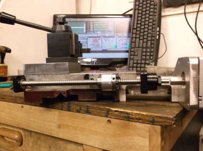
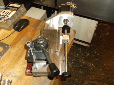
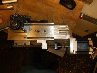
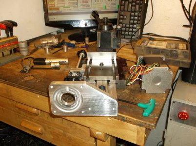
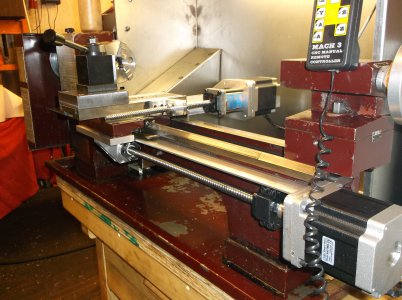
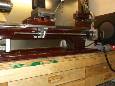
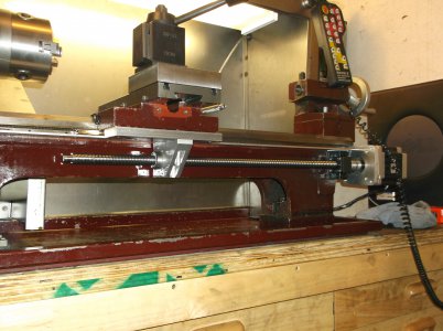
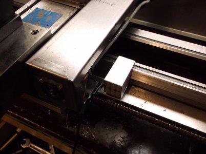
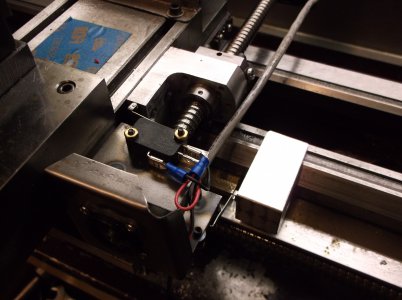
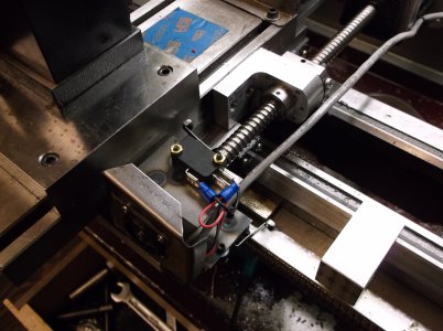
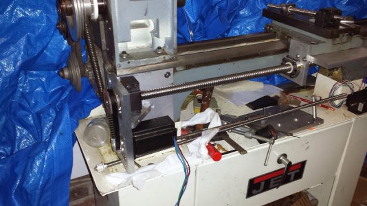
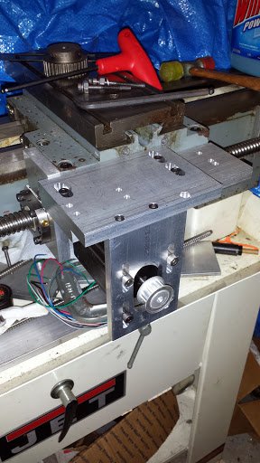
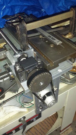
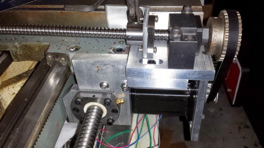
the x axis table was reversed and installed with the gib screws facing forward so the ballnut mount could be installed on the backside.
the ballscrew is a 1204
steve

DSCF1100.JPG DSCF1101.JPG DSCF1102.JPG DSCF1103.JPG DSCF1104.JPG DSCF1105.JPG DSCF1106.JPG DSCF1107.JPG DSCF1167.JPG DSCF1168.JPG DSCF1169.JPG DSCF1176.JPG
 
Thanks for the pics . They really help . I have 1204 & 1605 ball screws with 570oz steppers @ 50v . Im not sure If I should gear the motors down or run direct.
Either way thanks for the pics they really help me allot . Your design is one of the better ones ive seen . How does the brace help on the X axis , with the table over travel? Does it give it move support?
Mark
 
I cant see a problem with 570oz motors direct driving, your rapids may be a bit slower but that wont affect it's use during cutting operations.
I'm not sure what brace your asking about. If it's the brass part under the saddle in the front, that is an extended gibb, the original was too short and only supported cutting towards the chuck.
steve
 
Hi,
I have been working on a similar conversion, but I got stuck at the X axis part and have been letting it sit ever since.
I was working on mounting the motor up front with a belt drive and the screw on the headstock side since that looked like the only side with enough material for the ballnut mount.
Your approach seems much cleaner. It never occurred to me to flip the slide around so the mount could be on the right.
Can you post the dimensions of your X motor mount extension block thing?

Here are some pics of my current monstrosity.
Other issue is that carriage has some vertical motion due to the ball screw not being perfectly straight. I am hoping that replacement tension bars will take care of most of that.
Any thoughts or suggestions (or dimensions) would be appreciated.
Thanks,
John

20140203_213021.jpg 20140330_212938.jpg 20140331_073237.jpg 20140330_214714.jpg
 
Hi John
the extension I made to mount the motor on the rear is 4.5" long then there is a 1/2" plate extending to the right to mount the motor.
so the motor face is 5" beyond the end of the saddle.
I had a problem with ball-screw wobble and I had a bit of work to nullify the problem. my lathe saddle was worn and the v grove wear would let the saddle twist when changing z direction. I turned the saddle upside down on the mill table, placed a 1/2" rod in the v groove and measured down to the table. then I measured the flat area the saddle rides on in the rear to the table. I wrote down the difference between the 2. I then mounted the saddle square to the mill table at a 45 degree angle and recut the v groove with a 3/4 end mill. once the groove was redone I placed the saddle back on the mill table used the 1/2" rod in the v groove and slowly took the rear flat surface down until the difference matched what I had measured before. now the saddle traveled square and flat again. I made new brass full length gibbs for the front and rear. the original front one was short because the rear part was a lock plate to lock the z axis. I didn't need the lock now so I made the gibb full length.
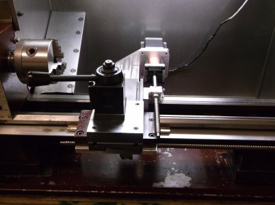
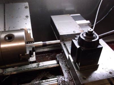
I tried at first to mount the motor at the spindle end and it was to close to the saddle, the imperfections in the screw would show up in the surface finish. I moved the z axis motor to the far end and didn't support both ends of the screw, just the motor end with a thrust bearing and coupling. that resolved all the finish problems and is plenty ridged to push and pull the saddle with only .0015 backlash.
I did all this testing before I had redone the saddle and it wasn't going to work until the saddle was redone. my v grove was just too worn to change z direction without pulling the saddle out of alignment.
I went back through the thread, I can't believe I didn't post about re-doing the saddle groove and gibbs. I'm going to see if I took pics but forgot to post them.
steve
 
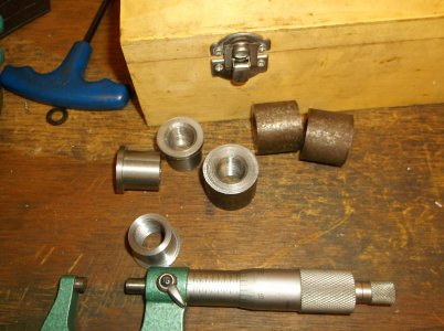
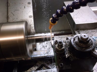
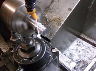
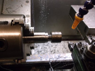
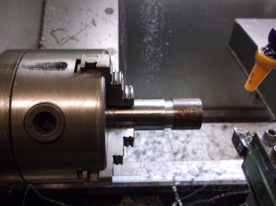
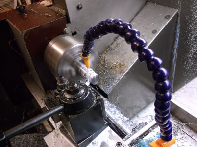
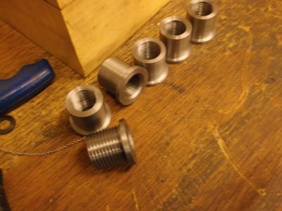
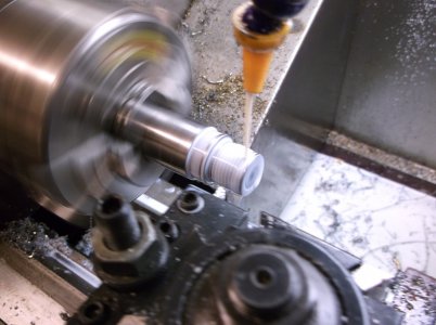
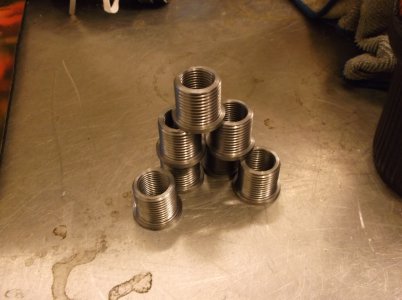
here is a batch of spark plug thread repair inserts I made for a friend.
from raw stock to part takes 27 minutes each, mostly because the internal thread is done before it goes on the cnc lathe.
I face, drill, and chamfer on my manual lathe then power tap on my mill and finish on the 9x20 cnc.
I have a lathe turret I'm going to tool to speed up the process on the manual lathe.
these inserts would cost him $27.00 each to buy from the retailer.
Steve

DSCF1845.JPG DSCF1846.JPG DSCF1847.JPG DSCF1848.JPG DSCF1849.JPG DSCF1850.JPG DSCF1851.JPG DSCF1852.JPG DSCF1853.JPG DSCF1854.JPG
 
Nice CNC machining, they look good. That's a real nice enclosure, with the built in lighting, for your lathe. Bob
 
Hello, do you still have your CNC converted 9x20 lathe? I also have a 9x20 lathe which I would like to convert to CNC having just successfully completed converting my Warco WM14 bench mill to CNC (I have included my build within a WM14 CNC conversion on this site). Do you still have any drawings or plans for the lathe conversion?

Kind regards
Martin
 
Back
Top