- Joined
- Dec 29, 2012
- Messages
- 394
This Power Supply Unit (PSU) is based on an old design by Steven Goodier, G4KUB and John Goodier, G4KUC
A friend of mine not wanting to purchase a commercial unit (as it is very expensive here) asked me if I could make for him a 13.8V 50A DC power supply.
Searching around I found numerous designs that I could use if I could find the heart of the PSU, i.e. the transformer, that could provide the required power.
After solving this problem by rewinding a Microwave Transformer (full story here) I decided to build a PSU the with the following features:-
• 50 Amps continuous output at a steady 13.8 volts.
• Over voltage protection.
• Under voltage protection.
• Short circuit proof.
• Current limit.
• Most of the smaller components to be mounted on a single PCB.
All components to be available “off the shelf”, plus a15.6 volt 50 Amp rewired MOT (Microwave Oven Transformer).
I estimated that the total cost of this power supply to be in the region of €50.00 when buying brand new components from ebay.
PART1 DESCRIPTION
Circuit Diagram
The full circuit diagram is shown in Figure 1.
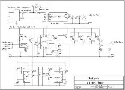
The heart of the power supply is the main control board, that contains 3 Integrated Circuits (ICs):
The 723 voltage regulator & current limit IC,
The 741 under voltage & short circuit protection IC
The mc3423 overvoltage protection circuit.
The protection ICs in the event of a fault occurring, will deactivate the circuit breaker relay which will cut the mains supply. Once the main control board has been made up, it is up to the constructor to decide how big or how small the final power supply will be. The final current rating of the supply will be determined by the choice of transformer, bridge rectifier, smoothing capacitors and pass transistors. With the MOT rewired transformer (used in my design), bridge rectifier and smoothing capacitors specified and using four 2N3771 pass transistors, the supply should be capable of producing more than 60 amps at 13.8 volts output.
A brief circuit description
The mains input can be taken to a 6 amp mains filter. This filter is optional and was not used in the prototype.
Protection for the P.S.U. is provided by a relay which in the event of a fault will disconnect the mains supply. This relay must have a 24 volt coil and is rated at 16 amps at 380 volts A.C. In the event of a fault the thyristor TH-1 grounds the coil opening the relay contacts and disconnects the mains. in turn the smoothing capacitors are discharged through R13 and TH-1. To start the supply SW-2 is pressed momentarily. This is a push to make switch and must withstand at least 10 amps. When pressed it shorts out the relay contacts and mains voltage flow to the mains transformer T-1 via the 50 ohm resistor R-15.
In-rush current circuit
The job of R-15 (50 ohm 50 Watt) is to limit the in-rush of current on switch on. The in-rush current happens because the smoothing capacitors are empty of charge and the transformer tries to charge them fully instantly drawing too many amps. Resistor R-15 allows charging to take place slowly thus protecting the bridge rectifier BR-1 (and the circuit breaker of the house). Inrush current equals 30 times the steady state current. The steady State Current = KVA of Transformer / Input Volts.
In my case, KVA of Transformer / Input Volts = 800/230 = 3,5A.
Inrush Current = 30 x 3,5 = 105 A (There is no domestic circuit breaker that allows that current!!).
Mains transformer
The recommended mains transformer is rated at 15.6 volts AC 50 amps and is a rewired MOT (Microwave Oven Transformer, you can read the full story of rewinding here).
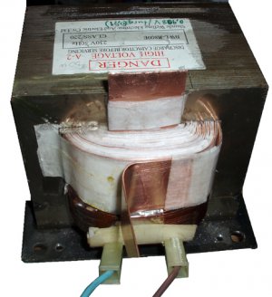
I would not recommend a secondary voltage of more than 18 volts. This is because the higher the secondary voltage is the more the pass transistors will have to drop to provide the 13.8 volts needed at the output. When high current is drawn a lot more heat will have to be dissipated by each transistor if the secondary voltage is high.
The output of the transformer is passed onto the bridge rectifier BR-1 which converts the voltage from A.C. to D.C. The rectifier can be of almost any type as long as it is rated higher than the expected current output. The prototype used a 100 amp, 1200 volt bridge.
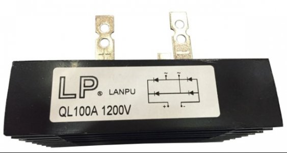
If wished individual power diodes can be used but in either case a heatsink will be needed. The bridge rectifier can be bolted to the chassis. The output from the bridge rectifier is passed onto the main smoothing capacitors Cx1 – Cx10. A good rule of thumb here use 2000 to 3000 uF per amp, so for a 50 amp P.S.U. a value of approximately 100,000 uF should be ample.
Voltage regulation
Regulation is provided by the popular (and old) LM723 which has appeared in many power supply designs over the last 30 years.
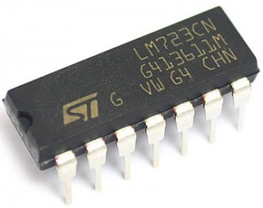
It has a maximum input voltage of 40 volts and very few external components are needed to get the IC up and running. It is also capable of providing current limiting and the IC is supplied in a 14 pin DIL package. The 723 is only capable of supplying about 150 mA, so a current amplifier transistor is needed to provide enough current to drive the pass transistors. This is taken care of by TR1 which is a TIP120 that increases the current available to drive the current hungry bases of the pass transistors.
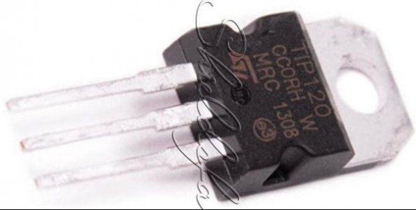
The output voltage is set by the resistor combination R3, R4 and VR-2. R3 is connected to the output to sense any volts drop and VR-2 is used to set the output voltage. As the load increases on our power supply, the voltage from the wiper of VR-2 drops as well. When this occurs, the 723 increases the voltage to pin 10 driving the pass transistors harder through Q1. So, the more base current flows through the pass transistors, the higher the output voltage will be. Thus we have regulation, the 723 continuously changing its output voltage to meet the minute changes in load on the supply. The output voltage swing should be in the region of 12 to 15 volts.
Cooling
All the current provided by the power supply need a regulating circuit that "burns off" the excess voltage, leaving only the desired 13.8V at the output. This is done by the pass transistors TR-2,3,4 and 5. The transistors used are 2N3771 which can handle a maximum current of 30 amps each.
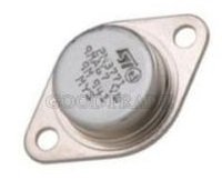
As you can imagine, it is not wise to run any device at its maximum rating. Thus for a 50 amp power supply you would want to have more than two 2N3771's in parallel. The bases and collectors of each transistor are wired together and each emitter has in series with it a 0.1 ohm, 20 watt resistor to ensure current sharing. The devices need to be bolted to heatsinks to ensure cool running, but it must be said when drawing 50 amps continuously they will run fairly hot. In this example think of the pass transistors as simply big variable resistors, as this is what they are really doing.
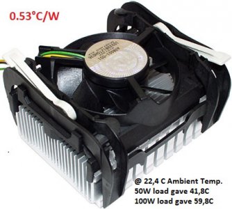
A little simple math shows the problem. For our example, we have an unregulated voltage of 22 volts and the load is 50 amps. Ohm's Law shows us that: 22 volts minus 13.8 volts = 8.26 volts drop across the pass transistors. 8.26 volts X 50 amps = 413 watts of heat to be dissipated! Best heat sink for that purpose proved to be a Pentium4 478 series (computer CPU) heat sink with fan for each transistor to keep temperature below 60C (having a load of 103W each and racing temperature 103*0.53 = 60 degrees at full power)!
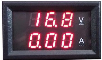
The outputs from the pass transistors are taken to the output terminals on the front or back panels of the case. The outputs can be taken to RED and BLACK terminal post. A red “ON” LED indicator (taken from the main PCB) and a Voltage & current panel meter are also wired to the front panel.
There is also a 0.1 uF capacitor wired across the output.
Current limiting
Current limiting is controlled by VR-1 and this facility is offered by the LM723 voltage regulator IC. Current limiting sets the maximum amount of current that the power supply will deliver and protects the supply from excessive currents.
Short circuit protection
This is provided by IC-2 an MC3423 over-voltage crowbar protector.
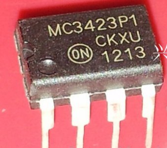
Voltage is fed back from the output to pin 2 of IC-2 via the resistor network R5, R6, and VR-3. The setting of VR-3 determines the firing voltage usually 15 volts for a 13.8 volt power supply. To prevent false tripping the MC3423 has a programmable delay feature. C7 determines the minimum duration of the over-voltage condition which will trip the protector. With the value in circuit this will be about 1mS. A value of 0.01uF will give a delay of about 0.1mS. When voltage rises above the pre-set level pin 8 goes high and fires the thyristor TH-1 which in turn grounds the relay coil, removes the mains supply and C1 to C10 are discharged via R13.
Under-voltage protection
An under-voltage circuit as been added to detect any drop in output voltage which could indicate a fault in either the power supply or the supplied equipment. It will also detect a short circuit on the output and in turn switch the supply off. The detector is built around a UA741 op-amp IC-3.
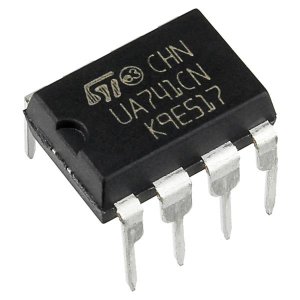
A reference voltage is generated via R9 and D2 and applied to pin 3 the non-inverting input. The output voltage is sampled by R10 and applied to pin 2. When the voltage drops below the reference voltage set by D2 pin 6 goes high firing the thyristor TH-1.
Components
Resistors: All resistors are 1/4 watt 5% apart from R13, R15 and R16 through to R19 .
R13 is a 2.2 Ohms 25 watt resistor constructed from four 10R 5W resistors connected in parallel obtained cheaply from e-bay.
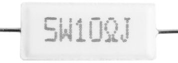
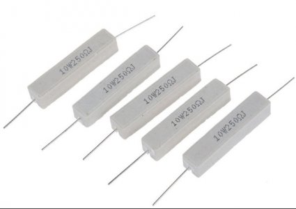
R15 is a 50R, 50 Watts constructed from five 250R 10 W resistors connected in parallel obtained cheaply from e-bay.
The current sharing resistors R16, 17, 18, 19 are 0.1 R 20W resistors and could also made up from paralleled pairs consisting of two 0.22R, 10 watt resistors.
Capacitors: All the capacitors are of common type. Smoothing capacitors can be obtained cheaply from e-bay. For instance 10 X 10,000uF at 25 volts cost around 5€.
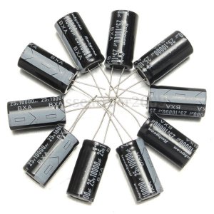
As we already stated the final value of C1, C2…Cx will depend on the final current rating of the supply.
Semiconductors: There should be no problem getting hold of any of the semiconductors for the project. Shop All semiconductors, transistors and thyristors are available cheaply from e-bay or from electronic parts retailers locally.
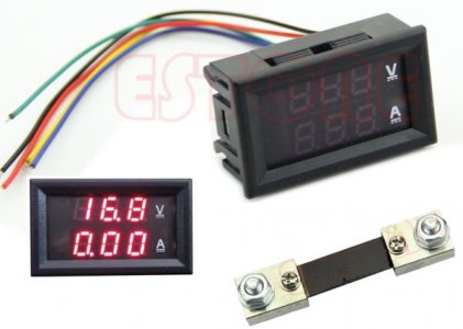
Miscellaneous: The 6 amp mains filter is an optional extra and was never fitted to the prototype. Make sure both switches are of a good quality. The relay RL1 must have a 24 volt coil. Most PCB type relays of the same size should fit the board and the PCB layout as taken into consideration the possible different pole arrangements. Other parts used, as an AC analog meter
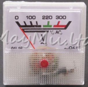
and a DC Voltage & Amp meter were bought from ebay.
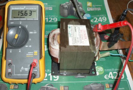
Microwave Oven Transformer: An 800W transformer was rewind, the secondary coil was made of 18 turns of Copper foil 0,6mm thick X 27mm wide. This gave an output of 15,63VAC @ 50+Amps (800W/15.63V = 51.2A).
Components List
Resistors
Reference Value
R1 10K
R2 3K3
R3 5K6
R4 6K8
R5 10K
R6 1K8
R7 1K8
R8 10R
R9 3K3
R10 10K
R11 10K
R12 1K
R13 2,2R 25 Watts (or 4 Χ 10R 5W)
R14 1K
R15 50R 50 Watts (or 5x250R 10W)
R16 etc. 0.1R 20 Watts
Capacitors
Reference Value
Cx1-Cx10 10,000uF /25 V
C3 0.1uF Disc
C4 4.7uF Tant 25 Volt
C5 100pF Ceramic
C6 220uF Elec 25 Volt Radial
C7 0.1uF Disc
C8 1,000uF Elec 25 Volt Radial
C9 0.1uF Disc
Semiconductors
Reference Value
IC1 = LM724 Voltage Regulator 14 Pin DIL
IC2 = MC3423 Overvoltage Crowbar Protector
IC3 = UA741 Op-Amp
TR1 = TIP120
TR2,3,4,5 2N3771
D1 1N4001
D2 12 Volt 1W Zener
LED Red
BR1 100 Amp High Power Bridge Rectifier
TH1 12 Amp Thyristor (BT152) or Similar
Miscellaneous Items
SW1 – Mains ON/OFF Switch Rocker or Toggle
SW2 – Good Quality PUSH TO MAKE
5 Amp Mains Fuse & Holder (10A for 115V)
RL1 – 24 Volt Coil Single Pole changeover Relay
T1 – 16.5 Volt 60 Amps Transformer from a 800W Microwave
Heatsinks 4 X P4 478 Heatsinks on 3mm aluminum sheet to host 4 TIP3771 transistors
High Current Wire: RED and BLACK (or copper strips)
Terminal Post made from 6mm 50mm long bolts
Terminal Block (12 and 30 Amp)
Push on solder tags to suit bridge rectifier (not needed if copper strips used)
Mains Cable 6 Amp
Printed circuit board, PCB Pen (nail varnish) and etch Case, Nuts, Bolts, Wire etc.
6 Amp Mains Filter (OPTIONAL)
To be continued with Part 2 CONSTRUCTION
Thanks for reading
Petros
A friend of mine not wanting to purchase a commercial unit (as it is very expensive here) asked me if I could make for him a 13.8V 50A DC power supply.
Searching around I found numerous designs that I could use if I could find the heart of the PSU, i.e. the transformer, that could provide the required power.
After solving this problem by rewinding a Microwave Transformer (full story here) I decided to build a PSU the with the following features:-
• 50 Amps continuous output at a steady 13.8 volts.
• Over voltage protection.
• Under voltage protection.
• Short circuit proof.
• Current limit.
• Most of the smaller components to be mounted on a single PCB.
All components to be available “off the shelf”, plus a15.6 volt 50 Amp rewired MOT (Microwave Oven Transformer).
I estimated that the total cost of this power supply to be in the region of €50.00 when buying brand new components from ebay.
PART1 DESCRIPTION
Circuit Diagram
The full circuit diagram is shown in Figure 1.

The heart of the power supply is the main control board, that contains 3 Integrated Circuits (ICs):
The 723 voltage regulator & current limit IC,
The 741 under voltage & short circuit protection IC
The mc3423 overvoltage protection circuit.
The protection ICs in the event of a fault occurring, will deactivate the circuit breaker relay which will cut the mains supply. Once the main control board has been made up, it is up to the constructor to decide how big or how small the final power supply will be. The final current rating of the supply will be determined by the choice of transformer, bridge rectifier, smoothing capacitors and pass transistors. With the MOT rewired transformer (used in my design), bridge rectifier and smoothing capacitors specified and using four 2N3771 pass transistors, the supply should be capable of producing more than 60 amps at 13.8 volts output.
A brief circuit description
The mains input can be taken to a 6 amp mains filter. This filter is optional and was not used in the prototype.
Protection for the P.S.U. is provided by a relay which in the event of a fault will disconnect the mains supply. This relay must have a 24 volt coil and is rated at 16 amps at 380 volts A.C. In the event of a fault the thyristor TH-1 grounds the coil opening the relay contacts and disconnects the mains. in turn the smoothing capacitors are discharged through R13 and TH-1. To start the supply SW-2 is pressed momentarily. This is a push to make switch and must withstand at least 10 amps. When pressed it shorts out the relay contacts and mains voltage flow to the mains transformer T-1 via the 50 ohm resistor R-15.
In-rush current circuit
The job of R-15 (50 ohm 50 Watt) is to limit the in-rush of current on switch on. The in-rush current happens because the smoothing capacitors are empty of charge and the transformer tries to charge them fully instantly drawing too many amps. Resistor R-15 allows charging to take place slowly thus protecting the bridge rectifier BR-1 (and the circuit breaker of the house). Inrush current equals 30 times the steady state current. The steady State Current = KVA of Transformer / Input Volts.
In my case, KVA of Transformer / Input Volts = 800/230 = 3,5A.
Inrush Current = 30 x 3,5 = 105 A (There is no domestic circuit breaker that allows that current!!).
Mains transformer
The recommended mains transformer is rated at 15.6 volts AC 50 amps and is a rewired MOT (Microwave Oven Transformer, you can read the full story of rewinding here).

I would not recommend a secondary voltage of more than 18 volts. This is because the higher the secondary voltage is the more the pass transistors will have to drop to provide the 13.8 volts needed at the output. When high current is drawn a lot more heat will have to be dissipated by each transistor if the secondary voltage is high.
The output of the transformer is passed onto the bridge rectifier BR-1 which converts the voltage from A.C. to D.C. The rectifier can be of almost any type as long as it is rated higher than the expected current output. The prototype used a 100 amp, 1200 volt bridge.

If wished individual power diodes can be used but in either case a heatsink will be needed. The bridge rectifier can be bolted to the chassis. The output from the bridge rectifier is passed onto the main smoothing capacitors Cx1 – Cx10. A good rule of thumb here use 2000 to 3000 uF per amp, so for a 50 amp P.S.U. a value of approximately 100,000 uF should be ample.
Voltage regulation
Regulation is provided by the popular (and old) LM723 which has appeared in many power supply designs over the last 30 years.

It has a maximum input voltage of 40 volts and very few external components are needed to get the IC up and running. It is also capable of providing current limiting and the IC is supplied in a 14 pin DIL package. The 723 is only capable of supplying about 150 mA, so a current amplifier transistor is needed to provide enough current to drive the pass transistors. This is taken care of by TR1 which is a TIP120 that increases the current available to drive the current hungry bases of the pass transistors.

The output voltage is set by the resistor combination R3, R4 and VR-2. R3 is connected to the output to sense any volts drop and VR-2 is used to set the output voltage. As the load increases on our power supply, the voltage from the wiper of VR-2 drops as well. When this occurs, the 723 increases the voltage to pin 10 driving the pass transistors harder through Q1. So, the more base current flows through the pass transistors, the higher the output voltage will be. Thus we have regulation, the 723 continuously changing its output voltage to meet the minute changes in load on the supply. The output voltage swing should be in the region of 12 to 15 volts.
Cooling
All the current provided by the power supply need a regulating circuit that "burns off" the excess voltage, leaving only the desired 13.8V at the output. This is done by the pass transistors TR-2,3,4 and 5. The transistors used are 2N3771 which can handle a maximum current of 30 amps each.

As you can imagine, it is not wise to run any device at its maximum rating. Thus for a 50 amp power supply you would want to have more than two 2N3771's in parallel. The bases and collectors of each transistor are wired together and each emitter has in series with it a 0.1 ohm, 20 watt resistor to ensure current sharing. The devices need to be bolted to heatsinks to ensure cool running, but it must be said when drawing 50 amps continuously they will run fairly hot. In this example think of the pass transistors as simply big variable resistors, as this is what they are really doing.
A little simple math shows the problem. For our example, we have an unregulated voltage of 22 volts and the load is 50 amps. Ohm's Law shows us that: 22 volts minus 13.8 volts = 8.26 volts drop across the pass transistors. 8.26 volts X 50 amps = 413 watts of heat to be dissipated! Best heat sink for that purpose proved to be a Pentium4 478 series (computer CPU) heat sink with fan for each transistor to keep temperature below 60C (having a load of 103W each and racing temperature 103*0.53 = 60 degrees at full power)!

The outputs from the pass transistors are taken to the output terminals on the front or back panels of the case. The outputs can be taken to RED and BLACK terminal post. A red “ON” LED indicator (taken from the main PCB) and a Voltage & current panel meter are also wired to the front panel.

There is also a 0.1 uF capacitor wired across the output.
Current limiting
Current limiting is controlled by VR-1 and this facility is offered by the LM723 voltage regulator IC. Current limiting sets the maximum amount of current that the power supply will deliver and protects the supply from excessive currents.
Short circuit protection
This is provided by IC-2 an MC3423 over-voltage crowbar protector.

Voltage is fed back from the output to pin 2 of IC-2 via the resistor network R5, R6, and VR-3. The setting of VR-3 determines the firing voltage usually 15 volts for a 13.8 volt power supply. To prevent false tripping the MC3423 has a programmable delay feature. C7 determines the minimum duration of the over-voltage condition which will trip the protector. With the value in circuit this will be about 1mS. A value of 0.01uF will give a delay of about 0.1mS. When voltage rises above the pre-set level pin 8 goes high and fires the thyristor TH-1 which in turn grounds the relay coil, removes the mains supply and C1 to C10 are discharged via R13.
Under-voltage protection
An under-voltage circuit as been added to detect any drop in output voltage which could indicate a fault in either the power supply or the supplied equipment. It will also detect a short circuit on the output and in turn switch the supply off. The detector is built around a UA741 op-amp IC-3.

A reference voltage is generated via R9 and D2 and applied to pin 3 the non-inverting input. The output voltage is sampled by R10 and applied to pin 2. When the voltage drops below the reference voltage set by D2 pin 6 goes high firing the thyristor TH-1.
Components
Resistors: All resistors are 1/4 watt 5% apart from R13, R15 and R16 through to R19 .
R13 is a 2.2 Ohms 25 watt resistor constructed from four 10R 5W resistors connected in parallel obtained cheaply from e-bay.

R15 is a 50R, 50 Watts constructed from five 250R 10 W resistors connected in parallel obtained cheaply from e-bay.

The current sharing resistors R16, 17, 18, 19 are 0.1 R 20W resistors and could also made up from paralleled pairs consisting of two 0.22R, 10 watt resistors.
Capacitors: All the capacitors are of common type. Smoothing capacitors can be obtained cheaply from e-bay. For instance 10 X 10,000uF at 25 volts cost around 5€.

As we already stated the final value of C1, C2…Cx will depend on the final current rating of the supply.
Semiconductors: There should be no problem getting hold of any of the semiconductors for the project. Shop All semiconductors, transistors and thyristors are available cheaply from e-bay or from electronic parts retailers locally.
Miscellaneous: The 6 amp mains filter is an optional extra and was never fitted to the prototype. Make sure both switches are of a good quality. The relay RL1 must have a 24 volt coil. Most PCB type relays of the same size should fit the board and the PCB layout as taken into consideration the possible different pole arrangements. Other parts used, as an AC analog meter

and a DC Voltage & Amp meter were bought from ebay.

Microwave Oven Transformer: An 800W transformer was rewind, the secondary coil was made of 18 turns of Copper foil 0,6mm thick X 27mm wide. This gave an output of 15,63VAC @ 50+Amps (800W/15.63V = 51.2A).

Components List
Resistors
Reference Value
R1 10K
R2 3K3
R3 5K6
R4 6K8
R5 10K
R6 1K8
R7 1K8
R8 10R
R9 3K3
R10 10K
R11 10K
R12 1K
R13 2,2R 25 Watts (or 4 Χ 10R 5W)
R14 1K
R15 50R 50 Watts (or 5x250R 10W)
R16 etc. 0.1R 20 Watts
Capacitors
Reference Value
Cx1-Cx10 10,000uF /25 V
C3 0.1uF Disc
C4 4.7uF Tant 25 Volt
C5 100pF Ceramic
C6 220uF Elec 25 Volt Radial
C7 0.1uF Disc
C8 1,000uF Elec 25 Volt Radial
C9 0.1uF Disc
Semiconductors
Reference Value
IC1 = LM724 Voltage Regulator 14 Pin DIL
IC2 = MC3423 Overvoltage Crowbar Protector
IC3 = UA741 Op-Amp
TR1 = TIP120
TR2,3,4,5 2N3771
D1 1N4001
D2 12 Volt 1W Zener
LED Red
BR1 100 Amp High Power Bridge Rectifier
TH1 12 Amp Thyristor (BT152) or Similar
Miscellaneous Items
SW1 – Mains ON/OFF Switch Rocker or Toggle
SW2 – Good Quality PUSH TO MAKE
5 Amp Mains Fuse & Holder (10A for 115V)
RL1 – 24 Volt Coil Single Pole changeover Relay
T1 – 16.5 Volt 60 Amps Transformer from a 800W Microwave
Heatsinks 4 X P4 478 Heatsinks on 3mm aluminum sheet to host 4 TIP3771 transistors
High Current Wire: RED and BLACK (or copper strips)
Terminal Post made from 6mm 50mm long bolts
Terminal Block (12 and 30 Amp)
Push on solder tags to suit bridge rectifier (not needed if copper strips used)
Mains Cable 6 Amp
Printed circuit board, PCB Pen (nail varnish) and etch Case, Nuts, Bolts, Wire etc.
6 Amp Mains Filter (OPTIONAL)
To be continued with Part 2 CONSTRUCTION
Thanks for reading
Petros
Last edited by a moderator:
