A Taper Attachment For The Craftsman Lathe

ML_Woy

Active User
Registered
Joined
Apr 28, 2012
Messages
138
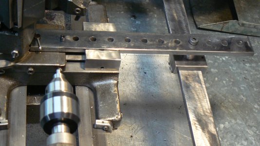
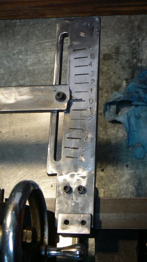
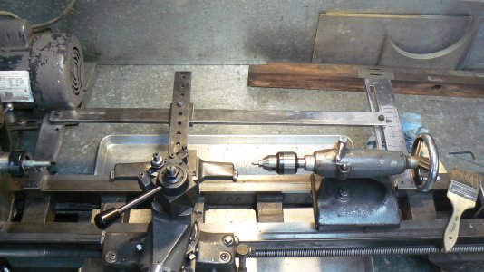
After watching video #71 from Tublicane, I decided to build a taper attachment for my lathe. I took some measurements from his attachment, turned on the CADD program, produced a drawing and began "making chips". Here are some pictures of the finished product. Not perfect but good enough for my shop.

Enjoy
P1090044.JPG P1090048.JPG P1090049.JPG
 
Last edited by a moderator:
ML,

That looks nice.
 
Your lathe resembles my Clausing MK2 enough for me to consider making one myself. How do you manage the slide effect on the compound?
 
Very nicely done!
What's your first project for it?

-brino
 
Nice job, I've been thinking of making one, I need to do an mt4 taper for my horizontal.
 
Your lathe resembles my Clausing MK2 enough for me to consider making one myself. How do you manage the slide effect on the compound?
The chip cover and the brass cross-feed nut are removed and the drawbar is connected to the cross slide by making a pin that passes through the hole that the cross-feed nut attached to on the cross slide. There is a small screw also in a pre-drilled hole in the Craftsman cross slide. A guide is machined to attach to the carriage dovetail. It is held in place with a set screw. This keeps the drawbar from rotating on the pin which holds it to the cross slide. On the other end a pin is inserted in one of the many holes in the cross bar which hooks to a car which rides on the "angle arm". As the carriage travels on the lathe ways, the cross slide moves in or out on your preset taper. Look at Tublicane's #71 video and he explains it a lot better than I can. I made mine much longer than the one he shows. The attachment points to the lathe ways are easy to make if you have flat ways. I used a double clamp method to make sure the attachment arms did not rotate. The depth of the clamping surface is only about one half of an inch.
 
Last edited by a moderator:
Nice job, I've been thinking of making one, I need to do an mt4 taper for my horizontal.
That is the exact reason I built mine as I needed to make a Morse taper to center my lathe chuck on my rotary table and a taper to hold my collet attachment in my tail stock. First project will be to make a Marlin spike for my brother.
 
Last edited by a moderator:
Nice job on the taper attachment. I also see that I am not the only one that uses an old cookie sheet for catching the majority of chips under the lathe.
 
ML that is brilliant . I haven't seen Tubal's tube clip on it though I have looked at a lot.
Would you be so kind and send me your plans or put up a link to them please?

The chip cover and the nut driving the cross slide are removed
I get the remove the chip cover .

But to my poor brain & thinking the nut driving the cross slide is the nut that holds the hand wheel to the screw thread , do you mean " Make it so that the operating screw thread of the cross slide is removed or disconnected from the half nut of the cross slide so the cross slide can slide freely back & forth when pushed / pulled by the arm on the sliding block of the taper attachment ?
 
Sorry, but I actually wrote that sentence (not ML), and I disagree. The special nut that retains the cross-feed crank does have a slight effect on the total backlash in the cross-feed as tightening it removes the end float of the jam nut. But if you remove the special nut and turn the crank without pulling on the crank (which would pull it off of the cross feed screw), the cross feed will work just as it normally does, albeit a little sloppily. Also, there is no half-nut in the cross feed system. The only half nuts (AKA split-nuts) are the pair on the back side of the carriage apron that engage the lead screw to traverse the carriage under power.

However, I will change the sentence to read "The chip cover and the brass cross feed nut are removed." My original was perhaps a bit verbose.
 
Back
Top