Adventures in my new-to-me Enco Lathe

Please let us know if you come up with a solution on your end. Thanks - Owen
Grizzly just responded that the part was indeed wrong, but that they don't have stock available. So I'm back to trying to find a pulley...
 
Grizzly just responded that the part was indeed wrong, but that they don't have stock available. So I'm back to trying to find a pulley...

I heard back from Grizzly as well. They did confirm that it was the wrong pulley, and I already have a return shipping label and return authorization # to send it back.

Vince C. in tech support is who I dealt with. He said their files indicated that the large pulley on the motor was supposed to be 95mm OD and the small pulley 63mm OD. He was unsure of pitch diameters.

I measured all my pulleys and did the math at pitch diameters as Larry$ suggested. My motor is 1725 rpm, not the 1750 rpm listed in the manual (and notice how Papa Charlie's is 1730 rpm???), so I used 1725 rpm in my calcs. I came up with needing a small pulley with a pitch diameter of roughly 51mm and a large pulley with a pitch diameter of roughly 79mm.

51mm is roughly 2" pitch diameter. Electricmotorwarehouse.com had a 2.1" pitch diameter and a 2.5" OD (very close to the 63mm Grizzly specified) with the correct bore and key dimension I need, which gets me as close as I could find for a small pulley. I already had a pulley on my motor with a pitch diameter of 85mm, which is pretty close to the 79mm pitch diameter I calculated, so I'll just use that in conjunction with the new 2.5" OD pulley that should be in here Saturday, and I should be right about where I want to be with speeds.

Vince also confirmed that the pulley should be installed on the motor the way it is pictured on Papa Charlie's lathe, not how it was installed on your Enco. This is the orientation that I figured may calcs on too.

So if I were in your shoes, I would get a 2.5" OD and a 3.75" OD pulley and install it like it is pictured on Papa Charlie's lathe. Hope that helps?
 
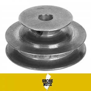
I think if you look around you can find a 2 step pulley that will come pretty close. Here is one example on Ebay of a 2"x3" Pulley with a 1/2" bore.

2 Step V-Belt Pully

s-l1600.png
 
I agree with Papa that you should probably use a two step pulley since the hubs may interfere with getting either both on the shaft or belt to align. I don't thing a bit of variation makes much difference to the lathe in actual use. All lathes are somewhat different in their speeds. Google two step pulley. Bet you can find the correct bore and approximate diameter needed. Cast iron would be better than die-cast.
 
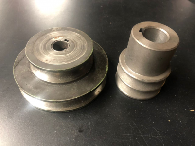
Problem I was having is finding the exact match, and the ones that were close tended to be lightweight cast and so modifying them wouldn't leave a lot of material left. I also really want the 4" size so it's been difficult.

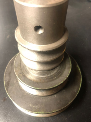
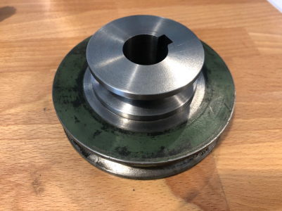
I recently got a new job and access to a machine shop with an on staff machinist I can talk to about it. My plan now is to modify the pulley that I got with the lathe that has a 4" and 3" steps. I scratched it with a file easily so it's not hardened. Since I have the other pulley to measure off of I'll just copy the profile and dimensions.
1598202750555.png
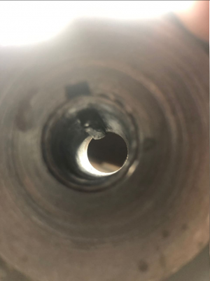
1598202854481.pngI'll probably need to buy a broach to cut the keyway.

I'm not 100% sure what's going on with this key/collar setup, but it looks like it should just press out
1598202893711.png

Though I'm tempted now to return the motor I just bought that has a 24mm shaft (or maybe 15/16" I need to mic it) for one with a 22mm or 7/8" which seem to be more common. Especially since they hosed me on the pulley I think I can get them to pay
 
Update on how things are progressing:
1598893080880.pngMachinist just finished the pulley modifications to the new 24mm motor shaft. Committed to the motor now, but at least I should be able to get low end speeds again. Also received a shipping notice that my toolpartspro order for the back gear. Will get in today so hopeful this one fits without issue and I can resolve that issue.

Last thing to figure out besides a new power cable is how to wire up the motor, and I'm thoroughly confused by the documentation.

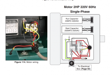
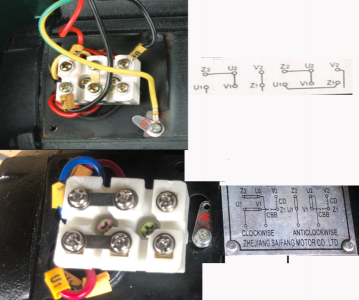
In the manual for the comparison grizzly this is what they show:
image.png

I zoomed in on the motor plate and here's a comparison between the two:
image (1).png

I see a few differences, such as how Z2, U2, and V1 are tied together in both directions in the manual, but on mine they need to be jumpered differently. (Note the jumpering on mine/bottom was how it was received. I'll need to modify it when I figure out how to wire.

If anyone has any insight into if I can follow the manual's wiring or if I need to change something please let me know (Larry maybe?) I'll spend some more time thinking about the logic, but reversing wiring is confusing.

Mike
 
As your motor came the jumpers are set for "clockwise" rotation. Following the diagram to reverse all you need to do is move the jumpers like show for anti- CW. Your power in, usually called "Line"are the two lines coming in from the bottom of the diagram. If this is for a 208/220 motor no neutral is used. The green wire, Ground, (green or yellow with green stripe,) goes to the screw with the little tab with the red markings. The feed from your motor control (switch) goes to the hookup shown as the two wires on the bottom of the diagram. Crimp some terminal ends on the wires if they are stranded. It pays to use the correct tools for wiring. One of the combination stripper, cutter, crimpers will work from the big box stores. A box of assorted wire terminals, will usually include hook, eye & splice with insulated crimp ends. Dedicated crimping pliers are nicer to work with but cost more. If you work on controls or motors with small, very fine leads, you will want to get a set of terminal crimp sleeves for inserting into the terminal connection blocks. Always use the correct sizes for the wire. using the wrong size will make for a poor connection. There are also solder terminals and heat shrink tube if you want to go that way. Always use solder meant for wiring, never any acid flux. You should be able to find good info on line.

As your shop grows and you get more advanced tools it will pay to learn about controls and wiring. Way cheaper to DIY than have a tech come in. Most electricians are not qualified to do even simple control wiring, I can tell you why, sometime.
 
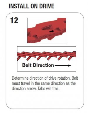
Just a note on the Fenner drive belt- orient the belt so "the tails follow". This will affect grip and noise level. Try it out next time you think about it.
203237-f20b2ca6edd22b629253c06f284d934c.jpg
 
As your motor came the jumpers are set for "clockwise" rotation. Following the diagram to reverse all you need to do is move the jumpers like show for anti- CW. Your power in, usually called "Line"are the two lines coming in from the bottom of the diagram. If this is for a 208/220 motor no neutral is used. The green wire, Ground, (green or yellow with green stripe,) goes to the screw with the little tab with the red markings. The feed from your motor control (switch) goes to the hookup shown as the two wires on the bottom of the diagram. Crimp some terminal ends on the wires if they are stranded. It pays to use the correct tools for wiring. One of the combination stripper, cutter, crimpers will work from the big box stores. A box of assorted wire terminals, will usually include hook, eye & splice with insulated crimp ends. Dedicated crimping pliers are nicer to work with but cost more. If you work on controls or motors with small, very fine leads, you will want to get a set of terminal crimp sleeves for inserting into the terminal connection blocks. Always use the correct sizes for the wire. using the wrong size will make for a poor connection. There are also solder terminals and heat shrink tube if you want to go that way. Always use solder meant for wiring, never any acid flux. You should be able to find good info on line.

As your shop grows and you get more advanced tools it will pay to learn about controls and wiring. Way cheaper to DIY than have a tech come in. Most electricians are not qualified to do even simple control wiring, I can tell you why, sometime.
Oh yeah I'm set up on wire terminals and recently "splurged" on a ratcheting. I engineer robots professionally so this is in my wheel house. Thinking about two logic states at once is just not something I do very often so I've been slow and cautious working it through.

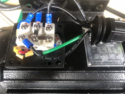
Here's where I'm at with the wiring but I just don't see how it will work based on what the manual shows for the wiring This is wired in supposedly the way they specify

A66018F1-65D1-4E3A-8E17-8B93B3C332E6.jpeg

For starters the motor won't change direction if there's a permanent short between u2 and v1 so I'm pretty certain that bar is wrong.

I'll draw out the wiring in cad a bit more and maybe things will become clearer


Just a note on the Fenner drive belt- orient the belt so "the tails follow". This will affect grip and noise level. Try it out next time you think about it.
203237-f20b2ca6edd22b629253c06f284d934c.jpg
great tip thanks!
 
Last edited:
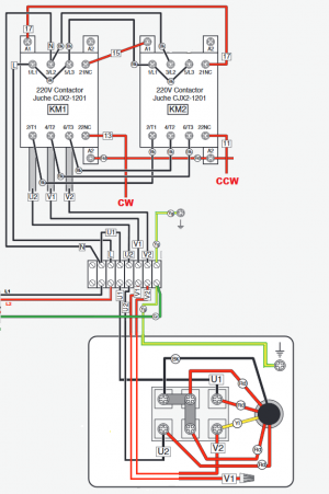
Combined and cleaned up the manual's wiring diagram to be a bit clearer:

Grizzly WIring.png

Going to recreate this image for my motor as well.

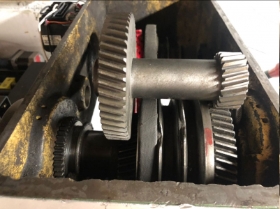
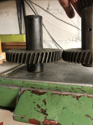
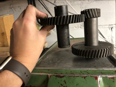
Also it looks like the back gear will work but I'm only getting ~75% engagement with the teeth which annoys me. I'm just never going to find the right back gear I fear.
1598976483593.png

Here's how it compares to the old one

It's a little thicker on the size of the gear:
1598983793810.png
Spacing from gear to gear looks a little more than what it came with:
1598983843308.png
 
Back
Top