Here's my source code for State machines...
Well, there are four state machines, els, stepPulse, edge and count
Somehow I managed to get all this in PIO0, using 31 of the possible 32 instructions!
Definitions...
OSR = output shift register. This is where data comes into the state machine. It's unfortunate that sometimes commands are referenced from the processors perspective and others from the state machine. You might think the out instruction is for working with data leaving the state machine, but it's referencing data output from the processor
.program els is the routine that handles the control words.
readControlWord:
This is where we start handing a new control word. The out x,5 instruction shifts the 5LSB's from the OSR into the x register. We've now got the bit count-1 in the x register. and proceed to waitForIRQ:
waitForIRQ:
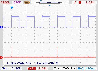
The edge state machine generates IRQ 5 on the rising and falling edges of the encoder phaseA. That provides 600x2 IRQ's per revolution of the spindle. Once IRQ5 is set, we proceed to testForStep:
testForStep:
out y,1 shifts the next control bit out of the OSR.
The jump instruction tests for zero and if it is zero, jumps to checkEndOfData:
If the control bit is 1, it fall through the jump an sets IRQ4 which will trigger the stepPulse machine to generate a stepper pulse.
checkEndOfData:
jmp x--, waitForIRQ is a post decrement test. In other words, the jump is determined by the state of X prior to the decrement. This is the reason why I save the number of bits -1 in the bit count.
if x is non zero, there are more bits in this word, so jump back to waitForIRQ.
if x is zero, the program wraps back to the beginning. I put a commented out jump instruction there to remind me where it's going next.
The inline code below the program is used to setup some of the commands.
.program els
; each control word consists of 26 control bits and a 5 bit count (msb-lsb = ControlBits-5BitCount).
; The 5BitCount indicates how many control bits are in the word -1 (-1 due to the post decrement test in jmp)
; Since we force empty the osr (out x,27) to support variable length control bit words,
; don't use 27 control bits (32-5).
; As a result of this limitation, use a maximum of 26 bits (25 in 5bit count)
readControlWord:
;read in the next control word bitCount
out x, 5 ;x contains the number of bits in the control word
waitForIRQ:
wait 1 irq 5 ;wait for the go signal
testForStep:
out y, 1 ; get the next control bit from the shift register
jmp !y, checkEndOfData ; if control bit is 0, no step, test for end of data
irq nowait 4 ; if falling through, control bit is high so make a step
checkEndOfData:
jmp x--, waitForIRQ
out x,27 ; empty the TxFifo (input to the state machine)
;jmp readControlWord ;Not needed since wrap does the same thing
% c-sdk {
static inline void els_program_init(PIO pio, uint sm, uint offset,
uint pulsePinA) {
pio_sm_config c = els_program_get_default_config(offset);
int pulsePinB = pulsePinA + 1;
sm_config_set_jmp_pin (&c, pulsePinB);
pio_sm_set_consecutive_pindirs(pio, sm, pulsePinA, 1, false);
sm_config_set_out_shift(&c, true, true, 32);
sm_config_set_in_pins(&c, pulsePinA);
sm_config_set_clkdiv(&c, 1);
// Load our configuration, and jump to the start of the program
pio_sm_init(pio, sm, offset, &c);
// Set the state machine running
pio_sm_set_enabled(pio, sm, true);
}
%}
.program stepPulse
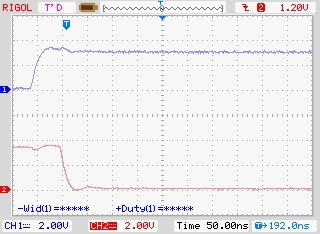
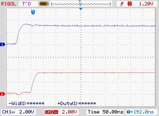
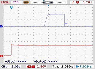
Simple program that waits for IRQ4 (set in els) and when it's set, waits 16 clocks to satisfy the setup time requirement between the direction pin and the stepper pulse (5us). After the 16 clocks, it generates a 5us pulse. The stepper driver pulse requirement is 2.5us.
The inline code sets up the state machine clock frequency so that clock period .5us.
.program stepPulse
;Creates a pulse with a user defined pulse width for the stepper motor
;setting clkDiv to 133 will result in a 1us clock.
;going to setup clkDiv to 133/2 (.5us)
;the 8us setup time is provided to meet the stepper driver direction pin to step setup time of 5us
loop:
wait 1 irq 4 [16] // should provide 8us setup time with clock set to .5us
set pins 1 [10] // provides 5us pulse, driver requirement is >2.5us
set pins 0
% c-sdk {
static inline void stepPulse_program_init(PIO pio, uint sm, uint offset, uint pin, uint clkDiv) {
pio_sm_config c = stepPulse_program_get_default_config(offset);
// Map the state machine's OUT pin group to one pin, namely the `pin`
// parameter to this function.
sm_config_set_set_pins(&c, pin, 1);
// Set this pin's GPIO function (connect PIO to the pad)
pio_gpio_init(pio, pin);
// Set the pin direction to output at the PIO
pio_sm_set_consecutive_pindirs(pio, sm, pin, 1, true);
// Set clock div
sm_config_set_clkdiv_int_frac(&c,clkDiv,1);
// Load our configuration, and jump to the start of the program
pio_sm_init(pio, sm, offset, &c);
// Set the state machine running
pio_sm_set_enabled(pio, sm, true);
}
%}
.program edge
This routine waits for high and low going pulses on the specified pin (pulsePinA in the edge_program_init program), and when either is found, generates IRQ5. This triggers els to start its processing.
I also use this routine to set the direction pin. I've defined phaseA and phaseB pins to be consecutive pins where phaseB is phaseA+1.
on the rising edge of phaseA, I check phaseB, if it's zero, I clear the direction pin. If it's high, I set it.
.program edge
;sets irq5 on any edge
loop:
wait 0 pin 0 ;wait for falling edge
irq nowait 5 ;set irq 5
wait 1 pin 0 ;wait for a rising edge
irq nowait 5 ;set irq 5
jmp pin forward ;if pulse pin is high we're going forward
set pins 0 ;not high, so set direction low
jmp loop ;start over
forward:
set pins 1 ;set direction high
% c-sdk {
static inline void edge_program_init(PIO pio, uint sm, uint offset, uint pulsePinA, uint directionPin) {
pio_sm_config c = edge_program_get_default_config(offset);
// setup the output pins
// Set this pin's GPIO function (connect PIO to the pad)
pio_gpio_init(pio, directionPin);
// Set the pin direction to output at the PIO
pio_sm_set_consecutive_pindirs(pio, sm, directionPin, 1, true);
// Map the state machine's OUT pin group to one pin, namely the `directionPin`
sm_config_set_set_pins(&c, directionPin, 1);
// setup the input pins
// set the jmp pin
uint pulsePinB = pulsePinA + 1;
pio_sm_set_consecutive_pindirs(pio, sm, pulsePinA, 2, false);
sm_config_set_in_pins(&c, pulsePinA);
sm_config_set_jmp_pin (&c, pulsePinB);
sm_config_set_out_shift(&c, true, true, 32);
// Load our configuration, and jump to the start of the program
pio_sm_init(pio, sm, offset, &c);
// Set the state machine running
pio_sm_set_enabled(pio, sm, true);
}
%}
.program count
Counts down from a preset value between rising edges. of the pulsePin.
When I setup this state machine, I programmatically load the OSR with a start count.
oneTime:
stores that count in the y register. Only executed the first time for the life of this machine.
The y register will be used to set the x register at the start of every cycle.
setup:
jump here on a rising edge.
Set activity high
Write the count to the input shift register (one of those weirdly named commands) input shift register is the output of the state machine.
load x with the value saved in y and decrement until the next rising edge is detected.
Be aware of this, since I need to be counting, I can't wait for the edges. I need to be polling for them while counting. It takes two instruction to perform the decrement and check for the pulse level while the pulse is high and while it's low.
decrement1:
I stay here while the pulse is high, constantly decrementing and testing for the pulse. As long as x isn't zero, the loop consists of the two jump commands. If x decrements to 0, I set activity to 0. When the pulsePin goes low, I fall through to decrement0:
decrement0:
the pulse is now low, we still decrement the count, and test for the pulse going high. Like decrement1, the loop is consists of two commands, jmp pin setup and and jmp x-- decrement0. If x decrements to 0, activity is set to 0. If a high going edge is detected, I jump to setup, reload x with y and start over. We're running!
For both the high pulse and low pulse sections, if x decrements to 0, I just remain in those sections. Decrementing x when It's zero is basically a NOP. The machine is stopped. when it starts again, the first rising edge will kick start the process.
.program count
;Used to calculate RPM of the spindle
;Counts down from a programmed value between rising edges of pulsePin
;The count is pushed into the rxFifo (output of the state machine)
;Any rising edge of pulsePin will set activity to 1
;if count reaches zero, activity is set to 0
oneTime: ;only executed one time
pull ;load the txfifo into the OSR
out y 32 ;store the initial count value
setup: ;come here on rising edge
set pins 1 ;activity high
mov isr x ;write count to RX shift register
push ;push it to the rx fifo
mov x y ;resture the initial count value
decrement1: ;count while pin is high
jmp x-- continueHigh ;decrement count
set pins 0 ;x=0 means no activity
continueHigh:
jmp pin decrement1 ;if pin is still high, go back
decrement0: ;pin is low, count until high
jmp pin setup ;found rising edge, done with this cycle
jmp x-- decrement0 ;decrement count
noActivity:
set pins 0 ;x=0 means no activity
jmp decrement0
% c-sdk {
static inline void count_program_init(PIO pio, uint sm, uint offset, uint pulsePin, uint activityPin) {
pio_sm_config c = count_program_get_default_config(offset);
// setup the output pins
// Set this pin's GPIO function (connect PIO to the pad)
pio_gpio_init(pio, activityPin);
// Set the pin direction to output at the PIO
pio_sm_set_consecutive_pindirs(pio, sm, activityPin, 1, true);
// Map the state machine's OUT pin group to one pin
sm_config_set_set_pins(&c, activityPin, 1);
//pio_sm_set_consecutive_pindirs(pio, sm, pulsePin, 1, false);
//sm_config_set_in_pins(&c, pulsePin);
sm_config_set_jmp_pin (&c, pulsePin);
// Load our configuration, and jump to the start of the program
pio_sm_init(pio, sm, offset, &c);
// Set the state machine running
pio_sm_set_enabled(pio, sm, true);
}
%}


