Another Igaging/touchdro Install

MozamPete

H-M Supporter - Gold Member
H-M Supporter Gold Member
Joined
Jun 26, 2014
Messages
619
I'm on a mission to try and finish off an embarrassingly long list of started, or equipment purchased for, but unfinished projects before I started/spend more money on anything new (I know there will be relapses along the way but at least it is a goal to aim for).

One such project that I had purchased all the equipment for but never go around to actually doing was to add a TouchDRO to my mill and lathe. (http://www.yuriystoys.com/p/android-dro.html)

I had purchased the basic iGaging remote display scales with the intension of getting them set up and working individually before interfacing them to a TouchDRO controller and tablet, so today I started with:

Mill X-Axis Scale Install
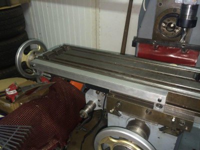
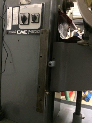
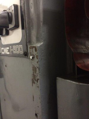
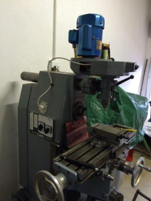
Like most people I think , I had originally hoped to install the X-Axis scale at the back of the table so it would be out of the way but eventually came to the conclusion that it would impact the Y-Axis travel too much. My mill only has about 5" of Y travel and at the extreme the table is hard up against the column so any installation at the back of the table would effectively lose about an inch of the available travel which was undesirable.

I also looked at the possibility of installing the scale under the table next to the lead screw but there just wasn't enough space. So in the end an installation at the front of the table was decided on.

My mill table has a T-Slot along the front which I had used for movable stops that I found very useful so this was a reluctant decision, but the only alternative I could find would of reduced by Y travel to 4" which would of been a bigger loss.
IMG_4389s.jpg
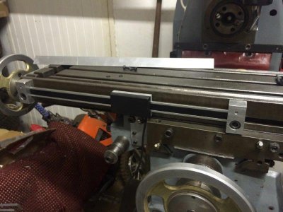
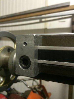
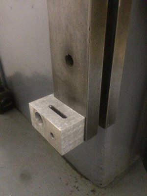
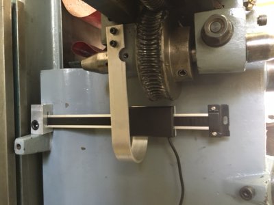
I decided to use the T-Slot for mounting and make it removable so I could avoid any drilling or permanent modification to the mill. By making new custom mounting brackets for the scale I also hope to crimp a little extra range from the standard 12"/300mm iGaging scale. My mill's X-Axis travel is 315mm and I was too cheap to buy a 24"/600mm scale and cut it in half. A 12" scale is actually 305mm of travel and has about 10mm of the scale clamped in the supplied brackets at each end. By reducing the amount of the scale in the mounting to 3 or 4 mm at each end I figures I could gain an extra 10 to 15mm and cover the entire possible physical travel of my table with a "12 inch" scale.

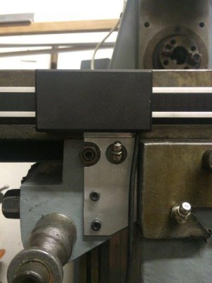
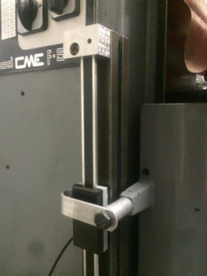
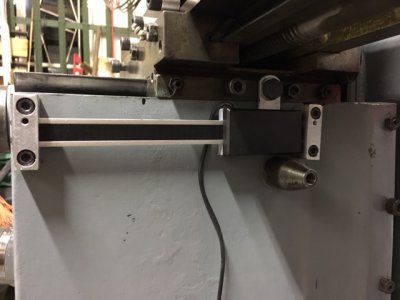
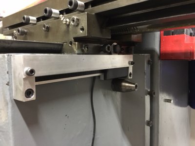
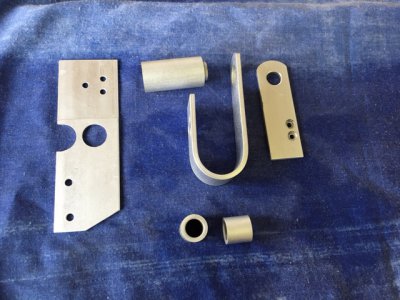
So after machining up two new end bracket that attach to the T-Slot and had a shallow milled pocket for the scale ends to fit into, and a bracket for the reader that fixed to two unused tapped holes that were added by the previous owner I had an installation that required no additional modification to the mill and can be easily removed is necessary.

The components:
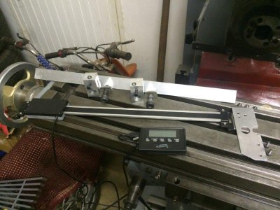
IMG_1410.jpg

Installed:
IMG_1411.jpg

Scale Bar Bracket:
IMG_1413.jpg

Reader Bracket:
IMG_1412.jpg

And with cover installed:
IMG_1415.jpg

One down, two to go.
 
Mill Z-Axis Scale Install
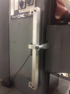
For the Z-Axis, after a bit of thinking and debate over how to install it I ended up going with a similar arrangement to what I had used on the X-Axis.

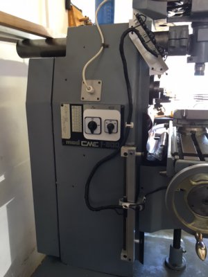
My mill has a cast iron T-slot block bolted vertically on the side of the column which coincides with a 'finger' on the knee casting for setting vertical stops. It is attached to the column with four counter bored M6 socket head cap screws and I decided to 'lightly' modify this to mount the Z-Axis scale - in line with my attempt to minimise the amount of permanent modification I made to the mill with the overall install.
IMG_1443.jpg

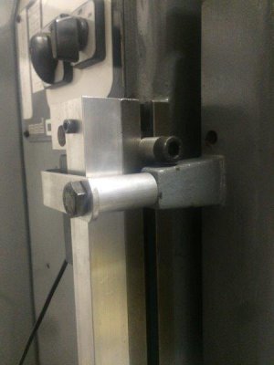
I replaced the top and bottom screws with M6 locating pins in the column (by simply turning down the heads of a couple M6 bolts), and then tapped the corresponding holes in the T-Slot block M8 to allow attachment of the scale mounting blocks. The T-Slot block is still held to the column with the original two central cap screws.

Locating pins:
IMG_1444.jpg

T-Slot block with scale bar mounting block attached:
IMG_1448.jpg

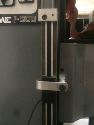
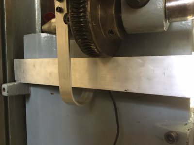
For the scale reader bracket I went with a hook that went over the reader and attached underneath to allow clearance to a chip guard that attached to the scale bar mounting blocks as I had done for the X-Axis. The reader bracket attaches to an existing tapped hole in the 'finger' of the knee via a long bolt and spacer tube.
IMG_1449.jpg

This arrangement allows an angle section chip guard to protect the front of the scale and fit between the reader and the bracket.

IMG_1451.jpg

At present both the X-Axis and Z-Axis chip guards are 25 x 25mm angle section which cover the cutter facing side so should provide adequate protection. If I can source some 25 x 50mm unequal angle I will replace them and the guards will then total cover the two exposed sided.

The possible knee travel is slightly longer than this arrangement allows for, but I don't realistically see me ever using the extremes (i.e. milling down into the table T-slots or working with something that large that the table has to be over 12 inches from the cutter). I have put in some hard stops on the T-slot to avoid possible damage to the scale if I were to accidently wind the knee too far. If working at the extremes of the knee travel was ever necessary it is only a matter of removing the one bolt holding the bracket to the knee finger to allow the full travel (but without the DRO scale working).

IMG_1453.jpg IMG_1450.jpg
 
Hey Peter nicely thought out installation! Thanks for sharing it is great to see how everyone solves these sorts of problems.
 
Mill Y-Axis Scale Install
After a false start I got the Y-axis installed this weekend. I had originally decided to mount it on the left hand side of the knee which had some advantages such as some existing threaded holes in the casting made by the previous owner which I could reuse, the fact that both the Y-axis and Z-axis scales were on the left so it would make routing the three cables to a common point nice and tidy and it would keep it out of the way of the gib screws and table locking screw which are on the right hand side.

I made up a mounting bracket for the scale bar and reader as for the other axis and mounted it up
image1.JPG

With the intension of using a cover cut to the contour of the knee as a chip guard
image3.JPG

But once I had it trial assembled I started to get concerned that there was too much flex in the reader bracket and I risked introducing some 'backlash' into driving the reader. As one of my main drivers for installing a DRO was to overcome the current backlash present in my old mills leadscrews that would sort of defeat the purpose. There was no simple way I could figure to shorten the bracket design on this side of the mill as I have the quick X-axis travel worm wheel to contend with.

So I scrapped that idea and went with moving the scale to the right hand side of the knee. This was a much simpler mounting but did require drilling and tapping a couple of new holes in the knee. I do still have easy access to the lock and gib adjustment screws, and the scale is positioned such that if I do build a drive motor for the X-axis (another project a wee way down the 'to-do' list) I can arrange it so that the shaft and gear fit around the scale.

image1x.JPG

And with cover installed. In this case the chip guard has a slot cut in the top for the reader bracket so it is not quite the 100% protection like the other axis, but anything the falls through the slot should pass behind the scale bar (and it is mounted under that table so the slot is only partially exposed at either extreme of the Y-axis travel).
image3x.JPG

Once it was all trial fitted up and I was happy with everything I decided to remove the components form all three axis and give them a final tidy up, filing the edges and any burrs. Then I gave them a soak in a caustic soda (lye) solution to matt the surface and hide any tool marks.

The reader brackets came out exactly as expected with a nice consistent matt finish.
image4.JPG

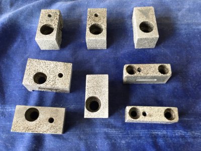
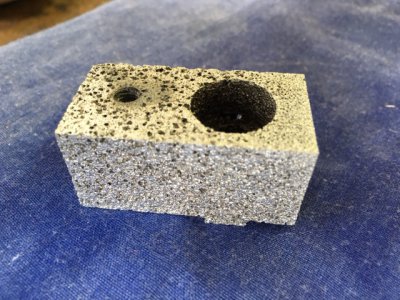
But the scale mounting bracket which I had machined out of some billets I had made with left over aluminium from my last casting project - OPPS
image5.JPG

image6.JPG

What looked like perfectly consistent aluminium following machining was heavily attacked and came out all pitted and looking like a piece of pumas. So the finishing process which I have used several times on component machined out of purchased stock doesn't work so well on the home cast stuff - Lesson learnt.

They are sill perfectly function but do look a bit strange - might end up painting them to match the mill.
 
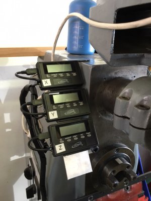
Knocked up a simple display bracket to temporary mount the supplied iGaging displays and routed the scale cables so I now have a functional system to use until I get the TouchDRO interface built.

The angle the bracket is at is quite steep, but that is just what worked with the lights in the workshop and getting the minimum glare when standing at the mill.
image1.JPG

Cables are just bound together with spiral wrap and held in place with stick on cable organiser clips (the type you use on your stereo cables, etc). I have some stainless steel braided cable sheathing which I will probably install for the final setup but that will likely require cutting the USB plug off the scale cable to install so will only go on when I am ready to wire them up to the TouchDRO interface module.

image2.JPG
 
A bit of advice, the original igaging scales used unshielded cables that are prone to pick up EMF noise from wires and motors.
They displays will jump around when you fire your mill up if it's going to be a problem.
If you need to change the cables, they are male to male mini-B cables and the only place I found that carries them are here: http://www.dcables.net/
Almost impossible to find on their site unless you have the part number, I'll see if I still have it.
If all else fails, I have 5 of them I ordered, but found I didn't need since I got the newer Absolute scales which come with shielded cables.
Another word of warning, to remove the cable from the scales, you have to remove the back cover. There's a spring under there that will go flying if you're not careful.
 
Thanks. I had heard that may be a problem which is why I planned to install a braided stainless steel sheath over each cable and earth it at one end (I already have some left over from another project). Only problem is the sheathing I have is fine for the cable but too small to go over the USB plug.
Once I have the Touch DRO interface module built I intend to finalise the routing of the cables, cut them to length, and solder them directly to the interface so will be able to install the sheathing at that stage.
Will see how it goes for now with the unshielded cables. Didn't notice any problems when using the vertical mill motor today, but haven't tried the horizontal mill motor which is larger and closer to the cabling.
 
Hope it all works out for you.
I can't wait until someone comes up with a fix to make the igaging Absolute scales work with Touch DRO.
 
When you cast do you use a flux to clean all the impurities out? I hate that when it happens. Nice job on the DRO
 
Super job so far. The touch dro work like a charm just make sure that you get a high resolution tablet for the app as it makes the interface much better. Where did you find the iGaging scales?
 
Back
Top