-
Welcome back Guest! Did you know you can mentor other members here at H-M? If not, please check out our Relaunch of Hobby Machinist Mentoring Program!
You are using an out of date browser. It may not display this or other websites correctly.
You should upgrade or use an alternative browser.
You should upgrade or use an alternative browser.
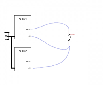
Anybody wire two VFD's to share the same estop switch?
- Thread starter CanFire
- Start date
- Joined
- Apr 12, 2013
- Messages
- 562
You may need to tie the neutral/0V/'ground' together to make sure the voltage references are to the same point. If this is a DC powered control circuit this will be an absolute necessity. If it is AC and off a grounded transformer it MAY work as drawn.
The classic industrial ESD wiring is to put everything in series. Any break in the loop shuts everything on the loop down. Multiple buttons (all wired through the NC contacts) become easy with this setup so you can ESD from multiple locations. While not typically useful on a single machine, if your 2 VFD's are in different locations that can be handy.
If there are continuing voltage mismatch problems, a isolation relay with 2 sets of contacts (DPDT) is the quick and easy solution. If you need more info on this solution just ask...
- Joined
- Aug 20, 2013
- Messages
- 20
Thanks CDH. Both VFD's will be on my mill - one to control the spindle and the other for the xFeed. In the case of an emergency, I would want to immediately stop both the spindle and the xfeed without having to hit two eStops so it's important that I get this right.
I wonder if I should even bother tying the chassis grounds together?
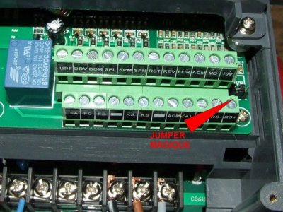
I believe this is a DC circuit as one of the terminals is called digital common. There is a V0 terminal as well though so I think I will tie the two V0 terminals together and measure if there is a voltage difference between the two DCM terminals. Ignore the arrow and red text in the image below - I lifted the picture off of the internet.

- Joined
- Apr 20, 2013
- Messages
- 210
Id just use a second NC contact on the estop and use the normal circuit in each VFD seperately.
- Joined
- Aug 20, 2013
- Messages
- 20
I had considered that option, but it would actually be a third NC contact as I was already planning to use a second NC contact to signal an off-delay-timer-relay to cut power to the VFD's after x.x seconds of DC braking.Id just use a second NC contact on the estop and use the normal circuit in each VFD seperately.
I did order eStop switches with stackable contacts so I can go crazy if I have to, but the final depth of the eStop switch might make it hard to find an enclosure.
Similar, but slightly different... I am leaning towards a friends suggestion of setting up another DPST relay circuit that is controlled by the eStop Switch and interrupts both VFD's independant eStop signals. It's starting to feel a bit excessive however and adds more electronics into the eStop circuit.
- Joined
- May 4, 2013
- Messages
- 249
What type of VFD's are you using? Many "Estop" inputs do not actually e-stop the drive. Most fancy drives that have this capability, refer to the input as a "safe off" input, and requires a dedicated loop, with current and pulse monitoring.
Most consumer level drives do not have this functionality, and therefore require a separate method of e-stop. The most common is a contactor which removes main power from the circuit. If you were to wire the coil of this circuit through your normally closed switch, you could feed both drives from it, still have your extra pole on the switch, and have a better Estop system.
-Cody
- Joined
- Aug 20, 2013
- Messages
- 20
Well, the Huanyang manual is incredibly vague about what happens when an eStop fault occurs and I haven't been able to find anything from other users on the internet. I'm hoping that the VFD does something different for an eStop condition than the regular stop.
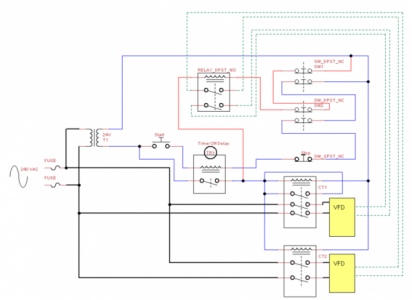
I don't know if anybody else can make sense of my (TinyCAD) wiring diagram, but here is the sixth revision:

The dashed green lines are the VFD's eStop sensing circuit. The eStops themselves are wired (red lines) to cut power to a relay which then interrupts the eStop sensing circuit of both VFDs. The blue lines are for the timer relay that cuts power to the two contactors that control power to the VFDs.
I don't know if anybody else can make sense of my (TinyCAD) wiring diagram, but here is the sixth revision:

The dashed green lines are the VFD's eStop sensing circuit. The eStops themselves are wired (red lines) to cut power to a relay which then interrupts the eStop sensing circuit of both VFDs. The blue lines are for the timer relay that cuts power to the two contactors that control power to the VFDs.


