Beauty in The Beast: Webb 5BVK Barn Find/Conversion

Excellent picture there @Charlieman22.

I'm not concerning myself with the end of the devise that holds the end mill (or other tool), except to say that ER is a good place to start, but with the opposite end that is pulled into the taper by the drawbar.

The pictured holder includes a "pull stud" which would be gripped and pulled by a drawbar typically used in a machining center with an automatic tool changer. The WEBB in question does not have an automatic tool changer and I suspect it does not use pull studs.

With the pull stud removed, the holder has threads where a threaded drawbar can be mated to pull it into the taper. Some different holder specs have different threads and lengths. You would need a draw bar with the correct thread and of the correct length to pull different holders.
 
That isn't precisely true.

The subject is covered, ad nauseum, on the web.

My understanding is, you could use either of those standards in an ISO40 spindle if you also exchange the drawbar.
In other words, the drawbar designed to pull one holder will not work on another.

Linked is a compilation of information on various spindle tapers.


I stand corrected, It looks like the difference is a m16x2 thread for the ISO, vs. a 5/8 -11 thread for the CAT, BT, and NT.
 
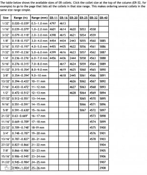
On the Collet end, there are different ER sizes, Size 40 which identies the outter dimensions of the collet would be a great place to start, then find a set of ER40 Collets that cover a reasonable range of tools that you can insert into them.

Here is a chart that shows the different collet sizes and the range of the tool they can hold. You can find a world of information on the web but this will give you a good range.

There are other types of collets, but the ER collets have a distinct advantage in that they have a slit in the front and back of the collet. This allows the collet to close on the held part evenly from both the front and back. Other types of collets only have the slit at one end. With those, as you clamp them down they only grasp the at the front of the collet and will get looser towards the back. This get worse the small the part is from the optimum holding size.

982f11ed5f3d7c709905e329d2cd4053a59178d9.jpeg

Here is some more reading on Collets that I think is really well done.

 
In other words, the drawbar designed to pull one holder will not work on another.
Clear.
I think I am going to start a list of "Milling Facts" that I can reference - this would be on there.

I'll have a read of that link. Very helpful.
 
To put a finer point on it, notice that the NMTB, ISO R 297-2583, DIN 2080 and similar holders are extended at drawbar end.

On the other hand, the CAT, CV, V-Flange and similar end at the small end of the taper (intended for use with pull studs).

To interchange, using threaded drawbars, different threads and different length drawbars are required in some cases.

I've read that there are some differences in the drive slots (in the flange) but I don't know the specifics. My impression is that the slot/lug differences are not a big problem and/or simple to accommodate.
 
Last edited:
To interchange, using threaded drawbars, different threads and different length drawbars are required in some cases.
This.

Before you jump in to the deep end, wait to get it home and then pull the drawbar out. Measure the threads - if it's a 5/8-11 then you have an NT40 taper. Also known as "NMTB40", "NST40" tapers.

The NT40 has a straight portion at the end that closely fits a cylindrical portion of the spindle ID.

https://en.wikipedia.org/wiki/Machine_taper#NMTB_taper_family

ISO40 is very similar with a straight section for the drawbar, but has a thread for a metric drawbar.

If it's not 5/8-11, report back and the hive mind will help you figure out what it is.

You can get/make a drawbar that will thread in to a CAT40 or BT40 holder, but NT40 holders are common enough there's not much point in having to swap drawbars. Especially since it already has a power drawbar actuator on it.

Once you get the drawbar measured and are fairly sure you have an NT40 taper spindle, buy ONE tool holder and see if it fits and the drawbar does what its supposed to do (i.e. tighten up and lock the holder in to the spindle).

The drive dogs in the photo are very narrow - you shouldn't have any issue with standard NT40 holder slots engaging the dogs properly. You really don't need the dogs until you start fooling around with 4" shell mills in steel.

After you verify the single holder fits, then you can spend all the money in the world on more holders. It'll feel like it anyway;)

Check the Webb brochure... I've highlighted the spindle specs.


-R
 

Attachments

  • Champ-5-VK-2017.pdf
    4.9 MB · Views: 3
Thanks gents.
Ok - I have a bit more depth on both spindle and drawbar now.
Will have a close look and report back - once I have the machine.

Now - about that stand.
This machine is unreasonably heavy.
I got a flavor of what it is going to be like to work with it today - while starting my rolling stand build.

My welding has been focused on cast aluminum - that while tricky to weld - is fairy easy to match strength of parent material.
The stand for a 4K# beast is another matter all together.

Had a good snoop around and saw a number of stands - mostly for Bridgeport types.
Decided I want to try and avoid creating a catch bin for chips and oil around the base - so designed something a little different.

Note to self: I hate hot rolled steel.

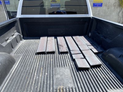
Truck loaded up - first inkling of just how heavy this thing was going to be.IMG_1924.JPG

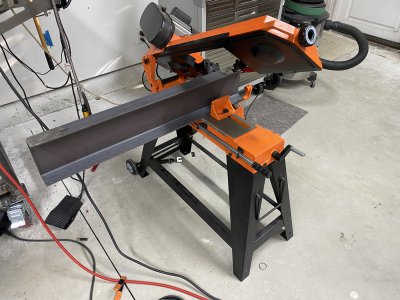
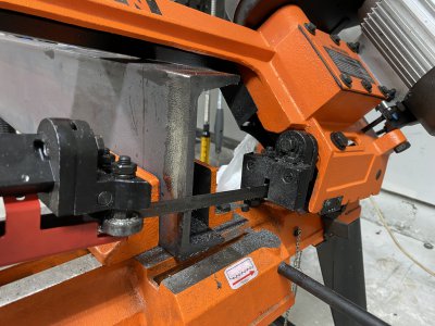
Bandsaw wouldn't fit width - so had to stand perpendicular.IMG_1952.JPG
As far as it would cut in one direction as neck hit my work - so I had to flip it.IMG_1954.JPG
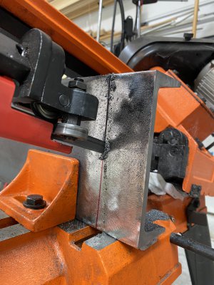
Note no witness line between the two cuts from separate directions. I think it is safe to say, that for as long as I am part of this community, I am likely never going to execute a cut better than getting this one perfectly straight with my wonky bandsaw.

IMG_1953.JPG

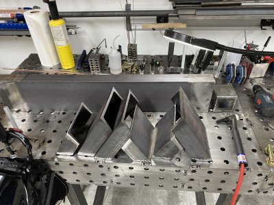
All the parts cut/descaled/beveled - to give my 220 amp welder any chance of penetrating properly.IMG_1944.JPG

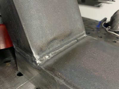
Sample of the outcome. I welded inside and out. Should be quite strong.IMG_1971.JPG

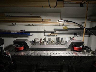
Beauty shot - this is the front frame. Its no light weight. There will be a matching one at the back - and they will be connected by a central beam. The casters are rated at 1200lbs ea - and will elevate the base about 1" from the floor. They are 7" wheels - so it should move around well enough.

The leveling feet will be kept, and during normal operation - the machine will rest on these - and the wheels will be elevated.
The worst part is still to come - I have to drill this 5/16" material - and... I don't have a mill.
Should wrap up tomorrow - and then pick up the machine on Thursday.

Cheers.
-CMIMG_1969 2.JPG
 
Nice work.

I am not so sure that you need the central beam, the machine itself will be your central beam once you bolt these two stands to the base. Not that it will hurt anything, just add more weight and use more material. Your weak point will be the welds on the wheel supports, that is where you will have the greatest stresses trying to pull it apart.

Regardless of with or without the central brace, I really like the design and concept.
 
Thanks Papa Charlie.
It was intended to be minimalist - you know - 200lbs of minimalist!
I agree - stresses will be concentrated at the welds and double beam may be overkill.
Perhaps single central will be final result.

Unfortunately - I am in the "there's a whole in the bucket" situation.
Drilling the holes will be an absolute bear.
I measured for them with the Mill on the ground - in a parking lot - with all sorts of stuff in my way.
Hope I got it right.

Plan to create 4 slots - two perpendicular, two horizontal - so I can have some wiggle room on fitting it up.
This is the kind fo drilling exercise that was part of my desire to have a mill.

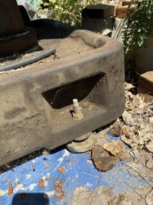
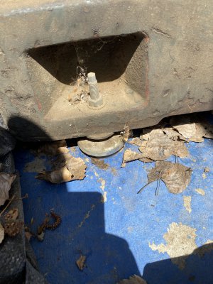
Below - the mill's base.
I'll add small extensions front and rear of the stand to hold the feet.IMG_1806 2.JPGIMG_1805 2.JPG
 
Back
Top