- Joined
- Feb 2, 2013
- Messages
- 3,627
I retrofitted a sinpak centrifugal start switch to my General Electric 1/2hp 1725 rpm 115v motor.

 www.hobby-machinist.com
it turned CCW by the OEM wiring.
i one up'd the manufacturer by making it turn both directions by means of an inexpensive 60amp drum switch

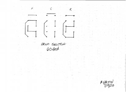
i first pinned out the drum switch

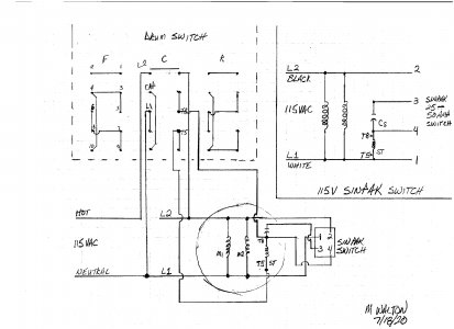
then i came up with the wiring diagram

T5 and T8 are the start winding ends.
when you reverse T5 and T8 the motor will turn the opposite direction,
given that the neutral and capacitor lead are also reversed in conjunction with T5 and T8.
i extended 4 leads out from the motor to hook to the drum switch for directional control.
i added incoming power and tested the motor.
with pride i can report, the motor turns both directions!
i made a video of the motor test and an explanation of the wiring.
if you have nothing better to do for the next 5:13 have a look!
as always thanks for reading and watching!

Centrifugal Start Switch Replacement/Retrofit
There are many ways to extend the life of older technologies by retrofitting them with newer technologies. My case is a perfectly functioning GE 1/2 Hp 1725 rpm 115v motor. i savagely harvested the centrifugal start switch, and tossed it aside to make way for a solid state relay made for...
 www.hobby-machinist.com
it turned CCW by the OEM wiring.
i one up'd the manufacturer by making it turn both directions by means of an inexpensive 60amp drum switch

60 Amp Drum Switch Forward/Off/Reverse Motor Control Rain-Proof Reversing 60A D | eBay
Wash-down Safe and Rain Proof. 3 Positions: Forward, Stop, Reverse. Switch Action: Maintained (Stay Switched).
www.ebay.com
i first pinned out the drum switch

then i came up with the wiring diagram

T5 and T8 are the start winding ends.
when you reverse T5 and T8 the motor will turn the opposite direction,
given that the neutral and capacitor lead are also reversed in conjunction with T5 and T8.
i extended 4 leads out from the motor to hook to the drum switch for directional control.
i added incoming power and tested the motor.
with pride i can report, the motor turns both directions!
i made a video of the motor test and an explanation of the wiring.
if you have nothing better to do for the next 5:13 have a look!
as always thanks for reading and watching!


