Cheap tachometer for LMS 3960 (Sieg SX2) machine

wbbaer

Registered
Registered
Joined
Nov 1, 2013
Messages
3
I found a way to get an accurate spindle tachometer reading from my LMS 3960 mill converted to CNC. I use Mach3 which accepts pulse input for spindle rpm. I used an infrared transducer mounted close to the spindle and reading the spindle lock hole. It remains accurate up to the maximum spindle rpm, 2500 and works with the LMS spindle control kit and Mach3 feedback loop. The transducer is about $25 plus shipping. If anyone is interested I will be happy to supply the details.

Bill
 
Bill, I think there will be quite a few members here who are interested in this addition. Please post.

Thanks.
 
We need pics of you installation also, it will help the members understand how you made it work. Tim
 
This scheme depends for spindle speed control on the use of the LMS control adapter (part no. 4213) but will work as a tachometer only, absent the spindle controller. Settings for feedback control of spindle speed are in the config: ports & pins: spindle setup menu. With the controller the PWM option is needed.

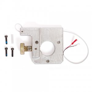
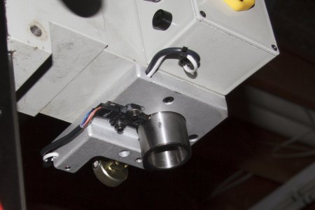
I used a transducer from Mouser Electronics made by Omron. Part no. is: EE-SY672. It is an infrared device which emits a continuous signal and receives interrupted reflections. I have it aimed at the spindle lock hole. The hole is centered in a plane about 9 mm below the bottom surface of the spindle casting. I have the spindle lock kit from LMS (part no. 4762). It is 12.5 mm thick at the back of the spindle hole. I machined a pocket in the lock plate for the transducer 3mm deep. Drilled and tapped holes for mounting as appropriate.

Wiring is simple. There are only three wires: +5v, gnd. and signal. See data sheet. I left fourth wire unconnected. I wired +5v and gnd. to the breakout board of my controller and the signal to an input line on the board. I specified this input as pin 1, port 1 in Mach3. Mach3 provides for spindle rpm input in the config: ports & pins menu and the config: general config menu. The debounce setting in the latter is important. Mine works with a setting of 30. There is a sensitivity adjustment on the transducer which needs tweaking for accurate reading of higher spindle rpm.

Attached are some useful documents. A photo of the installation, the transducer data sheet, photo of the spindle lock plate and my drawing for cnc milling. This drawing is incorrect and should not be used for an installation. It positions the transducer too close to the spindle. The gap should be about 5mm and this drawing puts it at about 3mm. The whole pocket should be moved back about 2mm.

Let me know if this needs clarification.

Bill

480.4762.jpg SpindleTransducer.jpg
 

Attachments

  • ee-sy671_672_dsheet_csm486.pdf
    424.2 KB · Views: 19
  • SpindleLockPocket.pdf
    11.7 KB · Views: 22
Back
Top