- Joined
- Sep 1, 2021
- Messages
- 20
I just finished running a 220v sub-panel over to where my mill is located and was looking for advice on wiring. When I purchased my Super 55 Wells Index the guy I got it from also provided an idle motor, magnetic contactor, general contactor, start capacitor, switch and timer. However, I am not quite sure exactly on the wiring...I thought a VFD might be an easier path and not sure if the rotary converter setup is right (I thought they need run capacitors as well?).
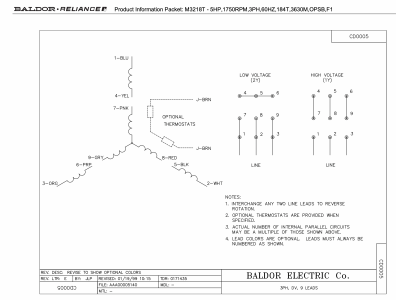
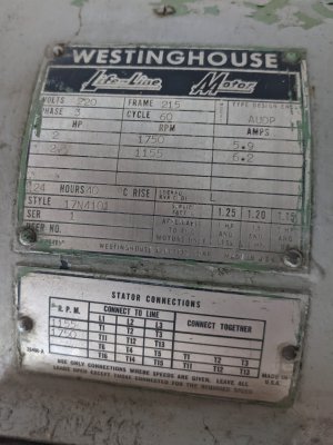
Here is the specs of the motor on my mill:
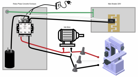
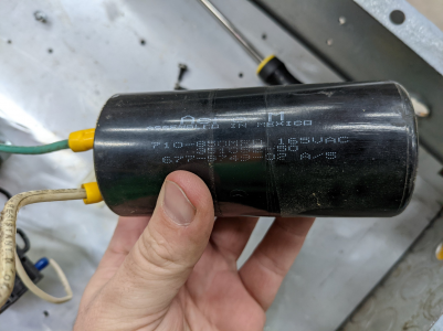
I am not really opposed to the rotary converter but the wiring feels like a spaghetti mess that I don't fully understand. The magnetic contactor is hooked up to a 120v cord where one legs goes to the coil and the other leg runs to a switch and one side of the capacitor through a wire nut...the other side of the capacitor was unplugged.
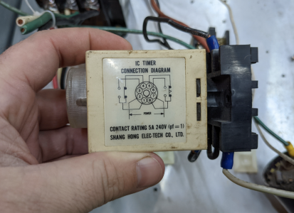
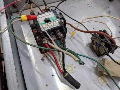
I assumed that 220v would come from my breaker into the 'L' side of the magnetic contactor (In the image below, the top right side closest to red chair). Currently there was a white and black wire snipped on the 'L' side but no ground...and what seemed strange to me was that there was a red cable that went from the 'L' side to the other smaller contactor that is in the middle of the panel. That smaller contactor is hooked up to a timer that the guy said he never really used, so...who knows lol.
On the 'T' side there is a red,white,black wire that has a black sleeve around it...I believe that may go to the idle motor and then the idle motor would be pushing back that 3rd phase on perhaps one of those 3 wires. Then I was thinking that the mill is also connected on those same leads, the other 3 wires that are zip tied together and therefor getting the 220v from the breaker as well as from the 3rd phase being generated?
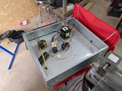
Here is the idle motor
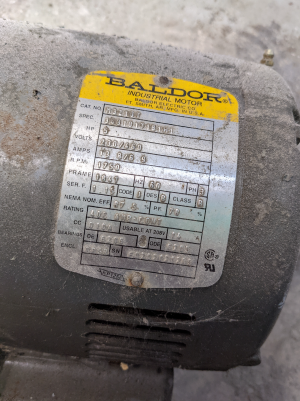
The magnetic contactor L side
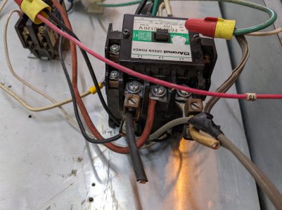
The magnetic contactor T side
For VFD was looking at this, which seems like it would be sufficient for size?
If anyone has any recommendations for either path I would greatly appreciate it. Been trying to restore a lot of pieces on the mill and would love to actually see it run. Going to be super bummed if it doesn't work and been burning time and resources.
Here is the specs of the motor on my mill:

I am not really opposed to the rotary converter but the wiring feels like a spaghetti mess that I don't fully understand. The magnetic contactor is hooked up to a 120v cord where one legs goes to the coil and the other leg runs to a switch and one side of the capacitor through a wire nut...the other side of the capacitor was unplugged.
I assumed that 220v would come from my breaker into the 'L' side of the magnetic contactor (In the image below, the top right side closest to red chair). Currently there was a white and black wire snipped on the 'L' side but no ground...and what seemed strange to me was that there was a red cable that went from the 'L' side to the other smaller contactor that is in the middle of the panel. That smaller contactor is hooked up to a timer that the guy said he never really used, so...who knows lol.
On the 'T' side there is a red,white,black wire that has a black sleeve around it...I believe that may go to the idle motor and then the idle motor would be pushing back that 3rd phase on perhaps one of those 3 wires. Then I was thinking that the mill is also connected on those same leads, the other 3 wires that are zip tied together and therefor getting the 220v from the breaker as well as from the 3rd phase being generated?

Here is the idle motor

The magnetic contactor L side

The magnetic contactor T side

For VFD was looking at this, which seems like it would be sufficient for size?
If anyone has any recommendations for either path I would greatly appreciate it. Been trying to restore a lot of pieces on the mill and would love to actually see it run. Going to be super bummed if it doesn't work and been burning time and resources.
Last edited:


