Closed Loop Stepper motor chatter at low speed causes?

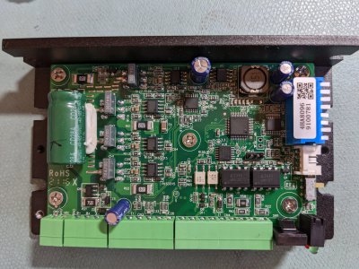
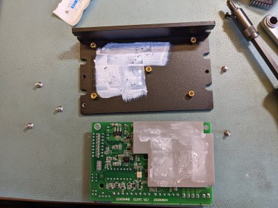
Opened the box. They painted over the part number for the processor, but that's pretty much normal. The power devices are on the bottom of the board and sandwiched against the heat sink plate. To take up the gap, they inserted an extra slice of insulator. The transistors are NOT physically attached to the heat sink with a fastener. Hey, that would be old school and cost a screw and a plastic insulator. So they saved 8 screws and 8 insulators. Otherwise, the board looks nice and dense. The dip switch is through hole. There's also a programming connector that was blocked by the cover. I presume that is how they flashed the processor. 4 pins. To get to the back side of the board, I have to disturb the driver transistors and the thermal paste, if there is any. I will loosen the 5 screws and see what happens... First need to put on an anti-static strap. You can see the anti-static mat. Well, it just lifts right off! Not much thermal compound there, but it does look like they used some kind of thermal compliant insulating mat.
PXL_20220917_182005185.jpgPXL_20220917_182855321.jpg
You can see it is a Ledshine CL57C V2.1 board. Hey, it's right on the silkscreen. On the top left side of the board is the dipswitch and its associated resistors. They look like 0603's. They are 4.7K ohm. The signal side, I think, is on the right side. Going to be tough to shoehorn the isolator in on the bottom side. Only have 4.8mm between the board and the case. Plus I need to come up with a connector with 4 pins for the diodes and somehow mount it. Would be a tricky packaging job. But the circuit is easy. Short across the pins horizontally. Need an SMT opto, with a height under 3.6mm. I could dead bug it. A standard DIP package is a bit thick.
 
Last edited:
Opened the box. They painted over the part number for the processor, but that's pretty much normal. The power devices are on the bottom of the board and sandwiched against the heat sink plate. To take up the gap, they inserted an extra slice of insulator. The transistors are NOT physically attached to the heat sink with a fastener. Hey, that would be old school and cost a screw and a plastic insulator. So they saved 8 screws and 8 insulators. Otherwise, the board looks nice and dense. The dip switch is through hole. There's also a programming connector that was blocked by the cover. I presume that is how they flashed the processor. 4 pins. To get to the back side of the board, I have to disturb the driver transistors and the thermal paste, if there is any. I will loosen the 5 screws and see what happens... First need to put on an anti-static strap. You can see the anti-static mat. Well, it just lifts right off! Not much thermal compound there, but it does look like they used some kind of thermal compliant insulating mat.
View attachment 420612View attachment 420613
You can see it is a Ledshine CL57C V2.1 board. Hey, it's right on the silkscreen. On the top left side of the board is the dipswitch and its associated resistors. They look like 0603's. They are 4.7K ohm. The signal side, I think, is on the right side. Going to be tough to shoehorn the isolator in on the bottom side. Only have 4.8mm between the board and the case. Plus I need to come up with a connector with 4 pins for the diodes and somehow mount it. Would be a tricky packaging job. But the circuit is easy. Short across the pins horizontally. Need an SMT opto, with a height under 3.6mm. I could dead bug it. A standard DIP package is a bit thick.
Dead bug is handy for this kind of thing.

You lucked out with the through-hole DIP switch, so hopefully the processor regularly checks the state(s) of the switches. Before making it nice and pretty-looking I'd do a quick manual test with the DIP switches to see if you can change the microstepping settings on the fly. That should be easy enough to do.

You may not need to mount the optoisolator on the back of the board. I see a couple of unused through-holes next to what is probably the processor (the quad leaded package). They're probably large enough in diameter to feed a couple of wire-wrap wires through each one. If not, you could remove the center brass standoff and feed wires through that hole. If there's space between the PCB and side of the enclosure that would be another option.
 
It appears that some versions of that stepper driver also have an RS232 interface. According to the data sheet I found, it can be used to control microstepping, uh, things. I said "things" because the data sheet was _extremely_ sketchy regarding that interface. Like not offering a single word on what what the commands are, or how they're formatted. What a tease, eh?

I note a white connector just below the DIP switch. I think that's where the RS232 connection may be. But the DS I found indicates it's a 6-pin connector while yours just has 4 pins (based on what I see on the bottom of the PCB).
 
Reverse engineering ICD's is not one of my strong points. The only possibility I see is to snoop the serial lines while exercising their Windows tool. Even that doesn't tell you everything. The connector appears to be 4 pins. It would be great to control micro stepping, that's really the only extra feature that I need. Otherwise, my controller (Teensy) doesn't know what the ustep settings are. Unpredictable results are not good for an ELS.
 
Opened the box. They painted over the part number for the processor, but that's pretty much normal. The power devices are on the bottom of the board and sandwiched against the heat sink plate. To take up the gap, they inserted an extra slice of insulator. The transistors are NOT physically attached to the heat sink with a fastener. Hey, that would be old school and cost a screw and a plastic insulator. So they saved 8 screws and 8 insulators. Otherwise, the board looks nice and dense. The dip switch is through hole. There's also a programming connector that was blocked by the cover. I presume that is how they flashed the processor. 4 pins. To get to the back side of the board, I have to disturb the driver transistors and the thermal paste, if there is any. I will loosen the 5 screws and see what happens... First need to put on an anti-static strap. You can see the anti-static mat. Well, it just lifts right off! Not much thermal compound there, but it does look like they used some kind of thermal compliant insulating mat.
View attachment 420612View attachment 420613
You can see it is a Ledshine CL57C V2.1 board. Hey, it's right on the silkscreen. On the top left side of the board is the dipswitch and its associated resistors. They look like 0603's. They are 4.7K ohm. The signal side, I think, is on the right side. Going to be tough to shoehorn the isolator in on the bottom side. Only have 4.8mm between the board and the case. Plus I need to come up with a connector with 4 pins for the diodes and somehow mount it. Would be a tricky packaging job. But the circuit is easy. Short across the pins horizontally. Need an SMT opto, with a height under 3.6mm. I could dead bug it. A standard DIP package is a bit thick.
I am using the CL57T driver and it has an RS232 port for external programming, microsteps being one of the parameters available. This may be an easier route for you.
 
I am using the CL57T driver and it has an RS232 port for external programming, microsteps being one of the parameters available. This may be an easier route for you.
You wouldn't happen to know what the actual serial commands are, would you? The actual byte string? I have V4.0, as marked on the outside of the case. If I could do that, it would be great, as that is easy. Is there a command to check the microstep settings, in other words a read back? Does one need to make the ustep setting, and then "tell the stepper controller" that the setting should be implemented? Or does the command alert the stepper controller to change the setting "automatically".

I found a MS10E.rar on the StepperOnline website. Inside the rar file, it contains CLSeries_setup.exe. I would need to run WINE on Linux to try this. Don't have WINE installed on this PC, but could do so. However, for a standalone ELS, I would have the Teensy serial port communicate with the stepper controller. That's why I am asking about serial commands and byte strings.

Do you know the connector pin out? Is it 3V serial, or really RS232 with bipolar levels? From looking at the PCB, I suspect the processor is 3.3V because there's a 3.3V regulator on board, the AMS1117-3.3.
The setup program might create a .ini file that contains relevant information. That makes more sense than hard-coding the information in the executable: but you never know. Another option is to look through your oscilloscope manual. Some can decode common serial data streams, which would make that part of the reverse-engineering somewhat easier (hopefully!). For the latter approach you will need WINE.

That doesn't answer your question regarding the connector pinout. But they sell an RS232 cable for not much: here. I think you know where to go from there :grin:
 
You wouldn't happen to know what the actual serial commands are, would you? The actual byte string? I have V4.0, as marked on the outside of the case. If I could do that, it would be great, as that is easy. Is there a command to check the microstep settings, in other words a read back? Does one need to make the ustep setting, and then "tell the stepper controller" that the setting should be implemented? Or does the command alert the stepper controller to change the setting "automatically".

I found a MS10E.rar on the StepperOnline website. Inside the rar file, it contains CLSeries_setup.exe. I would need to run WINE on Linux to try this. Don't have WINE installed on this PC, but could do so. However, for a standalone ELS, I would have the Teensy serial port communicate with the stepper controller. That's why I am asking about serial commands and byte strings.

Do you know the connector pin out? Is it 3V serial, or really RS232 with bipolar levels? From looking at the PCB, I suspect the processor is 3.3V because there's a 3.3V regulator on board, the AMS1117-3.3.
I was looking for the program that I used. I believe it is the same as in CLSeries_setup.rar. I'm no expert on this but it seems that setting the dip switches to 0000 allows software control of the driver.
 
The setup program might create a .ini file that contains relevant information. That makes more sense than hard-coding the information in the executable: but you never know. Another option is to look through your oscilloscope manual. Some can decode common serial data streams, which would make that part of the reverse-engineering somewhat easier (hopefully!). For the latter approach you will need WINE.

That doesn't answer your question regarding the connector pinout. But they sell an RS232 cable for not much: here. I think you know where to go from there :grin:
It seems like a good deal until you click on the shipping. $1.71 for the cable, $20.84 for shipping from China! Cable is $4.27 in Germany, but no shipping options. Can't seem to find the cable online elsewhere, yet.
 
Oh, there's another possible route to at least getting some information on the commands used. If they _are_ hard-coded in the executable it's very likely they are in a table that includes the ASCII commands. This is where the "dd" command-line utility could be your friend. That's very definitely hacker territory but could be useful to verify analysis results if you're monitoring the serial data stream.
 
Back
Top