Custom TX650 build log.

th62

Active User
Registered
Joined
Aug 22, 2014
Messages
315
I put this page together to document the steps in building the 74 TX650. With the exception of chrome work, upholstery and rebore, everything was done in my workshop. It's a public page, so no need to join.
https://www.facebook.com/groups/2008192399579556
 

Attachments

  • 374524751_3624308084495878_3540250346382255014_n.jpg
    374524751_3624308084495878_3540250346382255014_n.jpg
    225.1 KB · Views: 17
  • 348591104_3489338568051581_4603482796766752218_n.jpg
    348591104_3489338568051581_4603482796766752218_n.jpg
    712.5 KB · Views: 17
It came out amazing; nice work!
 
That is one smart looking conversion. I usually don’t like cafe conversions because few do them “right”.

Well done.
 
An engine removal thingie I made. 'Thingie' is a technical term for engine crane. XS650 engines are a very tight fit in the frame, only mms to spare, if you want to work on anything aside from the clutch and alternator,the engine must be removed from the frame.
The Thingie works quite well: Lifts the engine and tilts it forward so it can be rolled away from the frame without scratching or damaging the paintwork.
The thingie also doubles as a work stand for top end rebuilds.
When I've finished with the current work, I'll modify the stand so the engine can be mounted longitudinally in the thingie and rotated upside down to disassemble the bottom end.
Once the motor has been disconnected from all electrical inputs and front, rear and top engine mounts removed, the motor can be removed from the frame in around 5-10 minutes.
 

Attachments

  • 1.jpg
    1.jpg
    300.2 KB · Views: 10
  • 3.jpg
    3.jpg
    254.8 KB · Views: 8
  • 4.jpg
    4.jpg
    401.7 KB · Views: 6
  • WIN_20231014_16_00_29_Pro.jpg
    WIN_20231014_16_00_29_Pro.jpg
    362.7 KB · Views: 6
  • WIN_20231014_16_00_42_Pro.jpg
    WIN_20231014_16_00_42_Pro.jpg
    195.1 KB · Views: 7
  • WIN_20231014_16_01_53_Pro.jpg
    WIN_20231014_16_01_53_Pro.jpg
    197.8 KB · Views: 7
  • WIN_20231014_16_02_39_Pro.jpg
    WIN_20231014_16_02_39_Pro.jpg
    180.2 KB · Views: 10
  • WIN_20231014_16_02_53_Pro.jpg
    WIN_20231014_16_02_53_Pro.jpg
    302.6 KB · Views: 10
Some single use thingies: A cam chain holder to stop the chain dropping into the sump all the time. Better than string or wire because the motor will turn over.

A TDC finder. Made of an old plug which I threaded M10 internally, screwe a bolt in place, drilled and tapped that and screwed in a long M6 bolt.

The degree wheel is held in place by three rare earth magnets, it has marking for TDC and other markings 5 degrees apart up to 40 degrees. The short piece of tube, fits in the central hole and is a tight fit around the socket for centering. Once centred, it's removed to give the socket a little wriggle room.
 

Attachments

  • WIN_20231024_16_19_16_Pro.jpg
    WIN_20231024_16_19_16_Pro.jpg
    1.1 MB · Views: 1
  • WIN_20231024_16_22_37_Pro.jpg
    WIN_20231024_16_22_37_Pro.jpg
    372.4 KB · Views: 1
  • WIN_20231024_16_19_14_Pro.jpg
    WIN_20231024_16_19_14_Pro.jpg
    1.2 MB · Views: 1
  • WIN_20231023_16_12_23_Pro.jpg
    WIN_20231023_16_12_23_Pro.jpg
    308.8 KB · Views: 1
  • WIN_20231023_16_33_25_Pro.jpg
    WIN_20231023_16_33_25_Pro.jpg
    300.9 KB · Views: 1
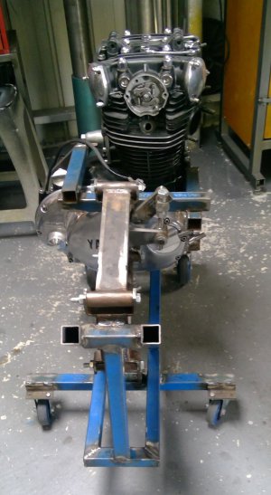
When I got the bike the cases had been damaged (read - rooted) by an errant chain. Along with that, the alternator cables had also been cut by the chain and the chain deflector, or whatever you call that thing residing over the gear lever pivot, was also stuffed.
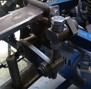
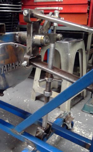
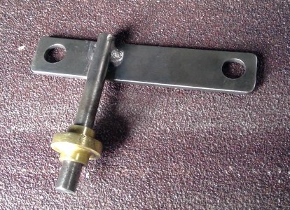
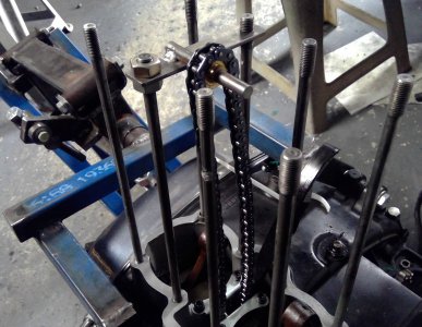
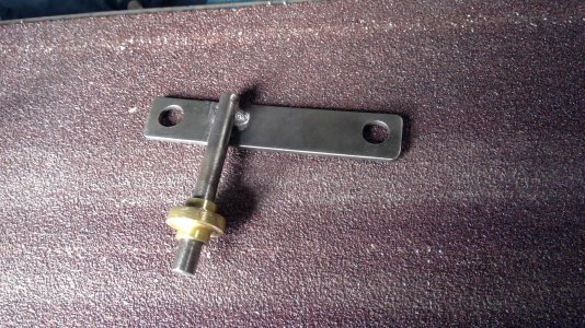
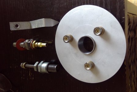
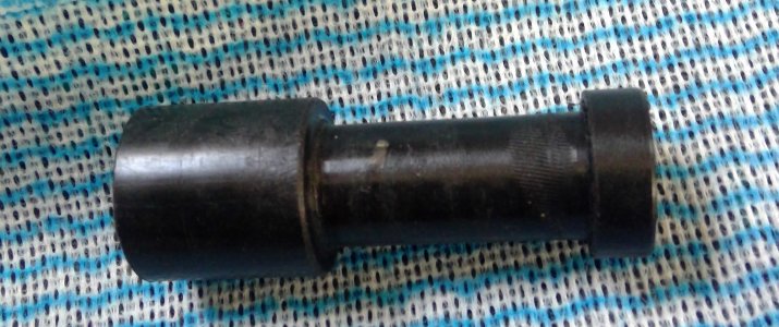
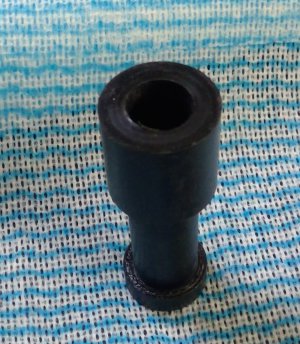
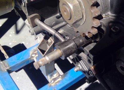
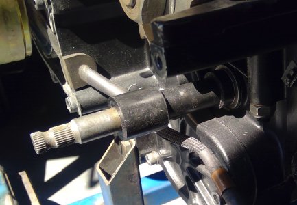
Rather than stick with the original design, I turned up a one piece Delrin bush which slides over the gear lever shaft. Rather than hide the alternator cabling behind the chain deflector, I rerouted the alternator cabling so it is underneath the gear lever shaft and held in place by a P clamp on the starter gear cover.
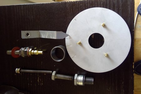
You may also be interested in making rubber grommets. In the pic you can see the rubber grommet through which the alternator cabling is routed. These, and other grommets, are super easy to make: A fibre cut off wheel and belt sander being all you need. Plus a good set of eyes, or in my case - glasses! The fibre cut off disks are good for cutting the slot, and either the cut off disk or belt sander to shape the outer circumference. Spinning rubber on a lathe does not work well, trust me!
After shaping the grommet, the groove or slot in the grommet is best made by mounting it on a piece of round stock and rotating it against the cut off wheel. Cut of wheels are generally available in two thicknesses 3mm and the much thinner ones used on small angle grinders. Obviously a good, solid rotating base will result in a better groove or slot. With a bit of practice , they are easy to make and come out as good as a bought one. In Oz, blocks of rubber are available from Clarks Rubber. I'm sure in whatever country you live there will be similar stores.
Never buy what you can make.
 

Attachments

  • WIN_20231018_11_18_32_Pro.jpg
    WIN_20231018_11_18_32_Pro.jpg
    559.3 KB · Views: 0
  • WIN_20231018_11_18_40_Pro.jpg
    WIN_20231018_11_18_40_Pro.jpg
    358.3 KB · Views: 0
  • WIN_20231018_11_21_20_Pro.jpg
    WIN_20231018_11_21_20_Pro.jpg
    389.9 KB · Views: 0
  • WIN_20231018_11_21_27_Pro.jpg
    WIN_20231018_11_21_27_Pro.jpg
    436.9 KB · Views: 0
Back
Top