

-
Welcome back Guest! Did you know you can mentor other members here at H-M? If not, please check out our Relaunch of Hobby Machinist Mentoring Program!
You are using an out of date browser. It may not display this or other websites correctly.
You should upgrade or use an alternative browser.
You should upgrade or use an alternative browser.
Dipping my toes into turning
- Thread starter koenbro
- Start date
- Joined
- Feb 23, 2016
- Messages
- 424
It's a through hole, will check if there is a narrow end and punch it out. Thanks @toprecyler and @Jim FIf it is a blind hole, grind a drill bit to fit and remove the pin. old FOMOCO tans. trick.
- Joined
- Feb 23, 2016
- Messages
- 424
Have received all the parts and have swapped out the motor; had to drill two new holes in the base. I then wired up the system so that I can test it (thank you @mksj for the recommendations, VFD settings, and wiring diagrams), and here is a video with its preliminary operation:
Also got a lamp and installed and wired it into 24VAC. Have added a global on-off switch so that the lathe is not under power all the time. Have removed the light on the front panel and have replaced the e-stop with a IDEC that is lit so I know if hte lathe is powered (plus the lamp. if left on, shows that as well). Will otherwise maintain the front panel although the gear levers are not necessary. What speed should I set them? Right now they are in the middle range (B-2 on my lathe).
The controls are all wired into the VFD directly, but if I understand correctly, best practices are to go through the contactors, so I will use the factory contactors, while removing the 240 motor wires. Seems like a waste of contactors to drive 24 V through them.
I will maintain the plexiglass shroud over the chuck as it seems like a good idea safety wise.
Lots of things still to do:
- Install the VFD and resistor into an enclosure
- Add EMI/RFI protection
- Wire into the contactors
- Wire up the jog -- I never used it during the entire 20 minutes of my life-long lathe experience, but seems like everyone loves it so will maintain it.
- Add an Omron encoder to show speed/RPMs using Clough 42'a ELS setup.
Last edited:
- Joined
- Feb 23, 2016
- Messages
- 424
I think I am done with the 3-phase conversion. This is how it looks:

The lower enclosure is my add-on. It houses the VFD, and the braking resistor. I also added a zero-phase reactor on the power-in side of the VFD, the top-left black structure. On the output side of the VFD I also added a line reactor (bottom left); all of this is intended to reduce EMI.

Will get some metallic conduit to place the power lines into it for protection.
Next will install the Clough42 ELS, in two separate steps: first the encoder, and electronics to read the RPMs of the spindle. Once that's done will add the motor and its power supply. This will be a bit of work as the lathe has no room to insert the servo, so will need a mount, etc
The lower enclosure is my add-on. It houses the VFD, and the braking resistor. I also added a zero-phase reactor on the power-in side of the VFD, the top-left black structure. On the output side of the VFD I also added a line reactor (bottom left); all of this is intended to reduce EMI.
Will get some metallic conduit to place the power lines into it for protection.
Next will install the Clough42 ELS, in two separate steps: first the encoder, and electronics to read the RPMs of the spindle. Once that's done will add the motor and its power supply. This will be a bit of work as the lathe has no room to insert the servo, so will need a mount, etc
If you can get some MC cable (armored cable like BX only it has an insulated ground wire) that would be ideal to replace the Romex. Otherwise flexible Greenfield will do the trick for you.
BTW, the NEC does not like multiple wires under one screw or nut (grounding or otherwise) unless the termination hardware is approved for multiple wire terminations. The correct way is a short piece of wire (aka pigtail) goes to the ground nut/screw and the others are wirenutted to that. You can also use the push in terminations you have, but a lot of electricians don't like them. The reason is misuse. Many push in terminations do not have a release mechanism, and pulling a wire out means it is now garbage. Too, you are supposed to use straight wire when you push it in (if it is solid), and not slightly curved. Each brand has its own instructions...and they should be read and followed. Many guys are not good at that.
BTW, the NEC does not like multiple wires under one screw or nut (grounding or otherwise) unless the termination hardware is approved for multiple wire terminations. The correct way is a short piece of wire (aka pigtail) goes to the ground nut/screw and the others are wirenutted to that. You can also use the push in terminations you have, but a lot of electricians don't like them. The reason is misuse. Many push in terminations do not have a release mechanism, and pulling a wire out means it is now garbage. Too, you are supposed to use straight wire when you push it in (if it is solid), and not slightly curved. Each brand has its own instructions...and they should be read and followed. Many guys are not good at that.
- Joined
- Feb 23, 2016
- Messages
- 424
That’s great to know about the code, thanks. Will redo the ground.
I hear you about the connectors that are single use. I use the Wago ones with the lever that releases neatly.
Sent from my iPhone using Tapatalk Pro
I hear you about the connectors that are single use. I use the Wago ones with the lever that releases neatly.
Sent from my iPhone using Tapatalk Pro
Last edited:
- Joined
- Feb 23, 2016
- Messages
- 424
Doing my first ever lathe project and of course I ran into some problems.
I am trying to cut to a shoulder but it ends up rounded. Are there some “best practices” on how to do it with inserts?
I am thinking of using a parting tool to define the shoulder first, then cut towards it.
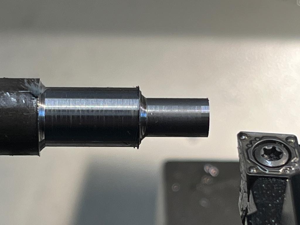
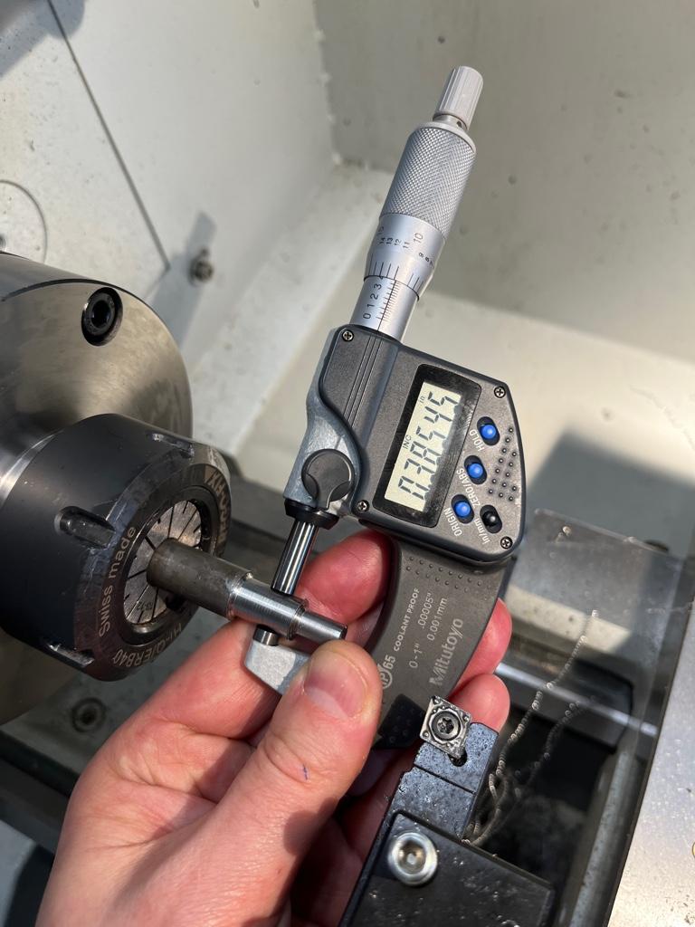
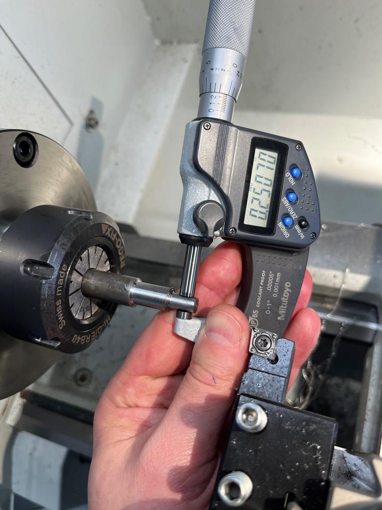
Otherwise I am satisfied with the dimensional accuracy. This is .500” 12L14 that I am trying to cut to .25” - .385” and drill/tap through.
Sent from my iPhone using Tapatalk Pro
I am trying to cut to a shoulder but it ends up rounded. Are there some “best practices” on how to do it with inserts?
I am thinking of using a parting tool to define the shoulder first, then cut towards it.
Otherwise I am satisfied with the dimensional accuracy. This is .500” 12L14 that I am trying to cut to .25” - .385” and drill/tap through.
Sent from my iPhone using Tapatalk Pro
Last edited:
- Joined
- Oct 11, 2016
- Messages
- 3,857
I'm not there, so I cannot be sure, but here's a couple of ideas...
Your insert seems to be rubbing. check that it is exactly on centre. Even .002 high is way too much for formed carbide. You can live with .002 low, however.
second your insert has a large radius. you won't get a sharp corner with that.
third - your insert is at the perfect angle - once it is on centre, you can use a facing cut toward your corner. you can then go to your diamter and move it unti it just touches and go toward your corner in the Z direction.
I hope these thoughts are helpful!
I probably know as much as you do about machining on a lathe (I'm mostly a wood worker). Once you have your diameter, why not use the compound rest to cut the shoulder (as if you were facing off the end)? Alternatively, if you want to cut toward the headstock, cut in, then back the compound rest out for your shoulder. Maybe lock the carriage when facing off the end and cutting a shoulder?
I'm not sure, but you shouldn't have the burr on the bar at the larger diameter (where your shoulder ends).
I'm not sure, but you shouldn't have the burr on the bar at the larger diameter (where your shoulder ends).