DIY air over hydraulic sizing.

Flynth

Registered
Registered
Joined
Dec 27, 2017
Messages
310
I'm in a process of building a 50ton (upgradeable to 150t) diy press. I already have all the materials and devices. I have done a lot of stock prep, hole drilling etc. I calculated the loads for a 1m by 0.5m size inside, but I'm having doubts if I shouldn't make it a bit smaller.

BTW, to calculate how the metal will flex I use a bunch of free android programs by one author. They have names like "frame design", "beam design" and "profile design" and red logos.

It is showing me 0.6mm(20 thou) deflection with this size and material I chose so I could build it like that. However I'm having doubts regarding size due to ease of moving it around etc.

I need the press mainly for forging, also some bending. Occasional repairs (pressing bearings) I know for sheet steel bending the bigger the better. But due to ease of moving etc I'm thinking about making it 80% smaller.

So I thought to ask here if there is something additional I should consider. Did you build a press and realise you would prefer bigger etc?

Or perhaps, you would prefer it smaller due to less flex? Maybe there is some use I'm na t considering?
 
Are you planning to use I beams, or square tubing for your upper and lower cross members? An illustration would help.
 
Are you planning to use I beams, or square tubing for your upper and lower cross members? An illustration would help.
Of course I'll describe it in detail, but please mind it is too late to change the materials etc(but size can be adjusted) . I bought the material few years ago (that's how long this project has been in the making) and most of it is already prepared.

Originally it was supposed to be 1m by 0.5m (40in by 20in).

I can make it smaller. Therefore more convenient to move. I would prefer that, but I'm not sure I'll not regret making it in the original planned (big) size later.

I'm looking for advice regarding what is a minimum convenient working area for a general purpose press. Perhaps my idea to use the press as a sheet metal brake in addition is not that great? Perhaps there is some use people have for their presses I'm not aware of now. I'll make it small, then I find out about it and I'll regret I haven't made it bigger... Then there are disadvantages to big size other than difficulty of moving it. One needs a very thick table to press stuff at full pressure etc.

So if anyone has built their own press please say how big is it, what do you use it for and if you wish it was bigger/smaller.

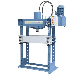
Answering hman's question. The shape is a typical H frame the same as all those cheap import presses advertised as 150 tons etc. There are 4 posts with holes in them. A table that can be lowered or raised and is locked in place by putting in pins that go through the holes in those 4 posts.

It will look similar to this:
06-1742xl_1_3.jpg
I definitely will put it on wheels, but they'll be raised normally so it will stand on feet. When there is time to move it the table will have to be moved to the bottom before wheels are used (to avoid tipping hazard).

Material-wise the 4 posts are 1in x 4in thick solid steel (S355 so slightly better mild steel). The table and the top part will be 8in by 3in C channel (all my steel is metric, I use English units, because that's what most people here use). The holes in 4 posts are 32mm (1 and 1/4th in) and the pins holding the table are induction hardened and chromed shaft. There will be extra bracing between the side posts on the bottom made of 8in wide 0.4in thick plate.

Construction is welded. I would prefer to make it modular, so the width can be changed etc, but the bolts required are quite expensive and rather than waiting longer for a good deal on them I decided to finish it now with welds. All welds will be done with my 350 amp mig rig, all will be notched and dual shield wire I bought years ago will be used for strength(I kept it home in its original packaging all this time).

Two pics of materials:
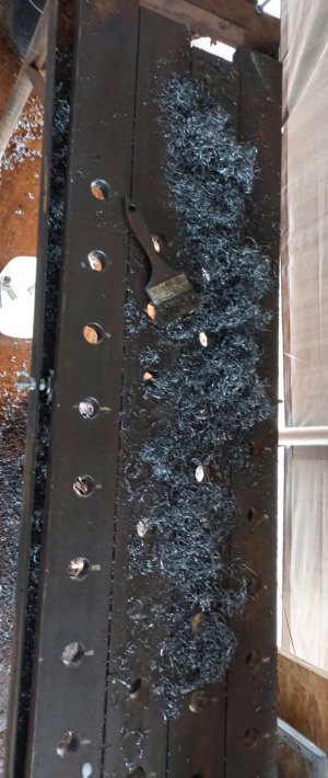
4 posts with holes drilled.
Compress_20230331_150913_3658.jpg
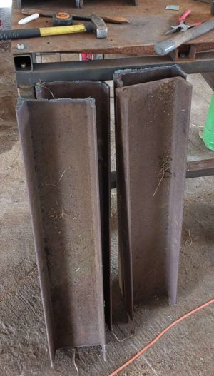
Some of that C channel roughly cut (it will be cut to final dimension neatly before welding).
Compress_20230331_150914_4002.jpg
 
!!! I would not use welds only to connect the posts to the top cross pieces or for anything that is expected to take 50 tons! IMO, Rated shoulder bolts or pins are the only safe way to make such joints. I also would at least triple the minimum sizes for the steel recommended on the app. presses are seriously dangerous at those pressures failures will happen instantly without warning. Be safe.
 
I'm in a process of building a 50ton (upgradeable to 150t) diy press. I already have all the materials and devices. I have done a lot of stock prep, hole drilling etc. I calculated the loads for a 1m by 0.5m size inside, but I'm having doubts if I shouldn't make it a bit smaller.

BTW, to calculate how the metal will flex I use a bunch of free android programs by one author. They have names like "frame design", "beam design" and "profile design" and red logos.

It is showing me 0.6mm(20 thou) deflection with this size and material I chose so I could build it like that. However I'm having doubts regarding size due to ease of moving it around etc.

I need the press mainly for forging, also some bending. Occasional repairs (pressing bearings) I know for sheet steel bending the bigger the better. But due to ease of moving etc I'm thinking about making it 80% smaller.

So I thought to ask here if there is something additional I should consider. Did you build a press and realise you would prefer bigger etc?

Or perhaps, you would prefer it smaller due to less flex? Maybe there is some use I'm na t considering?
Glad you said by one author, that raises a red flag. What if the author has a misconception, or wrong calc, and does it across all of the apps? Go find another author to verify the numbers, at 50ton quite deadly, at 150t, well, they may not recognize you if it lets go.
 
If you plan on making the press movable, don't put all the hydraulic equipment on the top. It will tip oven when moving. Double acting cylinder is very nice, springs are crap, You can use it as a puller, and you can use it to raise and lower the platen. Build work lights into the frame. If you are not a good welder then hire one. I have 50 tons, and a ac power pack, but I put a hand pump and a check valve so I am probably doubling the power( i use this feature carefully amazing things happen quickly) I have 36" x 12" with 48" useable Hight with 6" stroke cylinder. I find it to be to narrow, and i have cables and winch to move bottom plate it always jams and moves uneven.
 
Glad you said by one author, that raises a red flag. What if the author has a misconception, or wrong calc, and does it across all of the apps? Go find another author to verify the numbers, at 50ton quite deadly, at 150t, well, they may not recognize you if it lets go.
That's an interesting take I haven't thought of! I've been using those apps for years (usually for not critical stuff), but you're right, I'll check it elsewhere too.

If you plan on making the press movable, don't put all the hydraulic equipment on the top. It will tip oven when moving. Double acting cylinder is very nice, springs are crap, You can use it as a puller, and you can use it to raise and lower the platen. Build work lights into the frame. If you are not a good welder then hire one. I have 50 tons, and a ac power pack, but I put a hand pump and a check valve so I am probably doubling the power( i use this feature carefully amazing things happen quickly) I have 36" x 12" with 48" useable Hight with 6" stroke cylinder. I find it to be to narrow, and i have cables and winch to move bottom plate it always jams and moves uneven.

Thank you. This is very useful. What do you mainly use your press for? Mainly repairs etc, bending, forging? All of it?

Unfortunately, I'll have to initially use a 50t spring return cylinder I already have.

I noticed most presses shown on YouTube have a feature of movable cylinder (sideways) . It is usually done with locking rollers etc. Is it an important feature people use a lot? I was thinking about simplifying it and not having any rollers. Just a steel plate that can be loosened if required to move the cylinder assembly.
 
I have a hydraulic repair shop. So I'm pushing in bearing bushings, pushing out sized pins, final drives winch gear boxes. I some times hold cylinder rods to remove the nut. I also straighten bent rods with a big square tube diagonally in the bed with vee blacks.

My cylinder can be moved left to right but I never used that and found it made the cylinder flop around making bearings go in crooked, So I bolted it in tight.

If you think you might want to offset the cylinder just make a flange base that presses again the top frame, hang the cylinder on small bearings with a bolted down bracket to keep the cylinder tight when pressing.

I purchased the press from princess auto ( Canadian harbor freight) about 15 years ago.

Thanks.

I decided to make it slightly smaller. Rather than making the table 1m by 0.5m (40in by 20in) inside I decided to make it 0.8m by 0.5m (31in by 20in). I welded up the table today. Now I'm trying to figure out the best way to weld the legs while keeping everything in alignment. It is difficult stuff, because everything is so heave I'm not even trying to move it by gand. I have a little car engine lifting crane and I've been manipulating the heavy pieces with it.

Today is the first time I did some dual shield mig welding and now I understand why people love this dual shield rod. It welds great.it produces a very smooth arc, and one can lay lots of it quickly. I had to weld short sections of an inch or later two and going symmetrically to avoid warpage. Still immediately after making welds I would step back, look at my table. It would look crooked and as the weld cooled down it was pulled back into square...

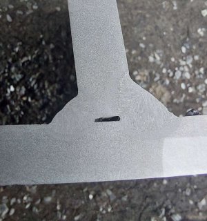
I did polish and etch on 3 different settings to see which one will be best. All 3 got good penetration. I was surprised having to polish it to very fine grit before it would etch properly (I never bothered to do an etch before, I just did destructive testing). Here is one example how it turned out:
Compress_20230402_023147_7992.jpg
This is 0.4in plate, different settings on both sides. The thicker side was 280A,30V, the smaller was 230A, 29V (co2 gas) . You can tell which weld was done first by the direction the plate leans at :).

Also, I don't think I'll be moving the cylinder much so I'll probably just bolt it in the middle. If I ever need to move it I can drill more holes and slide it.
 
Last edited:
!!! I would not use welds only to connect the posts to the top cross pieces or for anything that is expected to take 50 tons! IMO, Rated shoulder bolts or pins are the only safe way to make such joints. I also would at least triple the minimum sizes for the steel recommended on the app. presses are seriously dangerous at those pressures failures will happen instantly without warning. Be safe.

Sorry I missed your post before (I must have scrolled too quickly). Thank you for saying so. I would normally agree. An amateur welder should not attempt such critical welds(especially with a hobby size 200A machine) as any failure will be very dangerous.

I'm not a professional welder (far from it), but I'm quite confident in my ability to execute the welds correctly. Also I have the right equipment and materials to do it.

Regarding the app, I've verified the numbers for beam deflection and forces it gives me are correct. To clarify. I'm not using the app to tell me "this is the material size for this load you should use". It is more of a playground where you specify the forces, the material, loads and geometry. Then it gives you calculated deflections and loads within the material. It is up to the user to take this information and size their frame etc with the correct safety factor.

For those interested in more detail. All welds are stacked and they are T type welds. So far all welds are 1.5x base material size, but once I'm done I'might add more, but based on calculations they're more than enough (for example a 200mm long T weld of my current dimensions is supposed to have a breaking strength of 180 tons).

This brings me to another important topic. Pretty much every structural component will have high forces on it, but they will spread across a number of them. So although a single weld and every piece of that steel has over double the safety factor for the whole force it will never see it (unless during some sort of dynamic failure - that, and stiffness is why I planned them oversize).
 
Back
Top