- Joined
- Nov 23, 2014
- Messages
- 2,607
Back with another reproduction Erector set part string. This one was part number ‘B2’, red wooden-handled screwdriver. I’ll start with my customary long-winded history lesson. . .
The A.C. Gilbert Company was known for Erector sets and American Flyer trains. They also produced other toys like microscopes, Anchor blocks, chemistry sets, telescopes, puzzles, magic kits and carpentry sets. Gilbert was a master at “cross-pollenating” parts across their toy lines. For example, the caps used to secure the brushes on their small electric motors were also used as decorative tips on the magic wands in their magic sets.
Gilbert numbered Erector sets by size; bigger the number, the larger the set. In 1928, the largest set was a No. 10 and included one of the carpentry set slotted screwdrivers. The screwdriver was designated part# ‘B2’. The No. 10 sets included one of the ‘B2’ screwdrivers up through 1933. In 1931, Gilbert introduced the Erector Hudson locomotive and tender model and included a ‘B2’ in those sets up through 1934, maybe 1935.
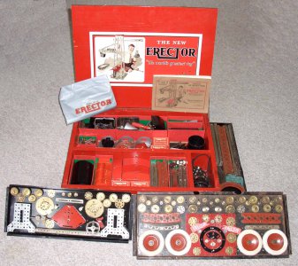
1930 No. 10 Erector set; you can see the B2 screwdriver in the bottom layer near the top.
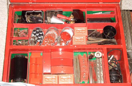
1931 No. 8 Hudson Locomotive Erector set, B2 is visible near the middle of the wooden box.
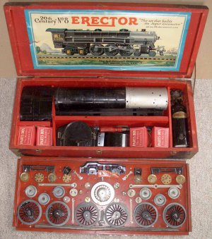
A lot of these sets are missing their ‘B2’ screwdriver. Probably because it was a handy size and was used for other jobs around the house.
There is actually a market for these. I’ve seen originals go for over $150 on eBay! Gilbert used the same wooden handle across the various tools included in their carpentry sets; a common practice is to pull the chisel blade, spokeshave, awl, etc. tool and replace it with a slotted screwdriver blade. These reproductions occasionally show up on eBay and bring around $80. The problem with those repros is the handle supply; you have to find a nearly 100-year-old tool set to make the reproduction ‘B2’. I made these repros from the ground up; better “business plan” as there are no supply issues for any of the components. I made the wooden handles from 1” birch dowels, ferrule from 303 stainless and the screwdriver blades from 3/16” 303. I’ll first go over the handle.
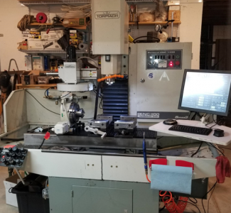
The handle has some shape to it and 8 flutes on the handle. My first thought was to make them on my Tormach 1100 mill which has a 4th axis. Chuck up a dowel between centers, cut the flutes with a ball-end mill indexing after each pass. Then change tools to a ¼” ball end mill to do the majority of the shaping; rotate the dowel with the 4th axis as the end mill burrows away. Then some finer grooving with an engraving bit. Though this process would let me start the cycle and walk away, I went the manual route (for now).
I ended up making a scraping tool from some 3/8” thick O-1 tool steel for the majority of the shaping. Started by milling a rake angle on the top, Dykem’d the top surface and scribed the two radii. Rough cut on the Bridgeport, then belt sanded & die filed to the scribe lines. Set the scraping tool to an original handle to verify the shape. I didn’t show it, but ground in a front relief angle with a die grinder and belt sander. The handle has a couple of grooves for “styling”; I marked their position on the scraping tool and center punched a line. Photos of this stuff are below.
Handle process was to first route the flutes into 3’ long dowels, cut them to length, and do the lathe work holding the dowel with a 5-C collet. Flute-indexing was done with an indexing plug that screws to the end of the dowel from 3/4" aluminum; the groove is only 0.030" deep so no fear of the router bit hitting the plug. The indexing plug had a shoulder a touch over 1/2" long turned to 5/8" diameter. Then to the Bridgeport and a dividing head to countersink 8 holes on 45 degree spacing and scribe a tick mark on the indexing plug. I used a mill/drill bit for that work.
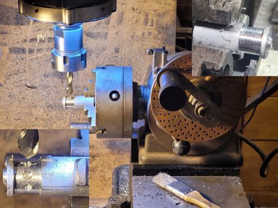
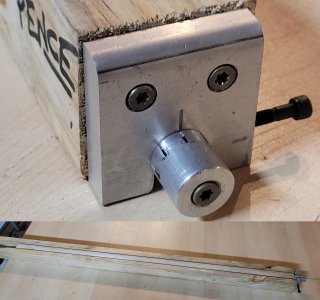
Mounted the indexing plug vertically on the BP, found center with an SDA laser center finder, and drilled a couple of holes for finish nails. In use, the plan was to chuck up the dowel on the lathe, center drill and drill a hole for a deck screw which would lock the indexing plug to the dowel. The finish nails dig into the dowel and help the indexing plug from slipping.
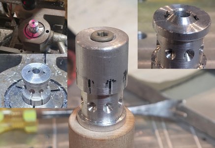
Made a indexing collar that the indexing plug shown above slips into. Drilled and tapped a hole in the side for a cap screw with a pointed tip that slips into the countersunk holes in the indexing plug.
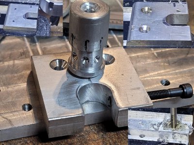
I didn't show the table saw/joiner work, but cut a little over 1" wide dado a little shy of 1" deep in the center of a 3x3. I went a little shy on the depth to ensure the dowel was slightly proud of the bottom of the 3x3. My worry was if a dowel had a little warp in it, the bit wouldn't cut to a uniform depth. Screwed the indexing plug to a dowel, slipped over the indexing collar, and set the assembly in the 3x3 for alignment before drilling the pilot holes and screwing the indexing collar in place. And some of the dowels were slightly warped; a "frown" shape resulted in a shallow cut in the middle. Easy fix was a second pass pushing down on the 3x3 to flatten the dowel.
I didn't have a 1/8" ball-end router bit, so made an arbor on the lathe for a 1/8" end mill. Mounted that in a router, adjusted the bit height
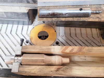
Fluting process was to screw the indexing plug to the end of a center-drilled dowel, set the dowel in the 3x3 and lock the plug in place with the cap screw in the collar. Make a pass on the router table, loosen the cap screw, rotate to the next mark, tighten the lock screw and repeat.
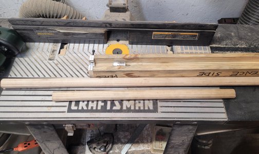
Once the flutes were in, the dowel was cut into individuals. Once on the lathe, center drilled, shank drilled and mounted between centers. Used the forming tool to scrape the shape into the dowel, pencil-transferred the groove positions, cut the grooves with a sharp threading tool, relieved the transition between the flutes and handle radii with a parting tool, filed in radii at the grooves/flutes, and sanded with 180-grit paper. Flipped the handle and worked a radius into the butt-end with a file/sanding block.
Scraping tool; rake angle cut on the BP, Dykem layout work, roughed on the BP, sanded/die filed to the scribed line and spot checked against an original handle.
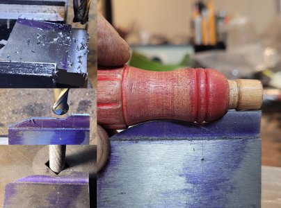
Dowel blank being scraped to shape. The handle has a couple of decorative beads; scraping tool has those locations center punched for easy pencil-line transferring.
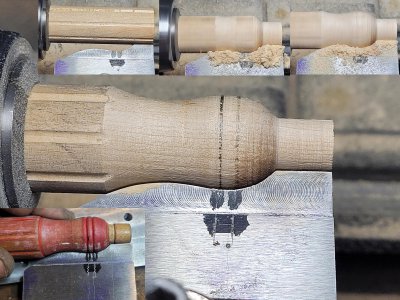
Cut the two grooves, then a flat at the flutes/radius, flipped the handle for facing and adding a radius to the end. The red handle is an original, bare one is my prototype.
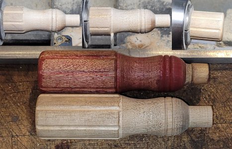
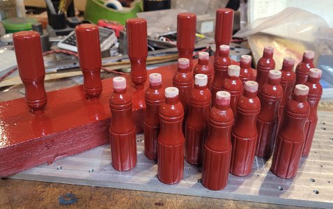
I didn’t show it, but did some clean-up on the flutes at the bench. The ends of the flutes had a little tear-out from cutting in the radii which were cleaned up with a needle file mounted in a cordless drill. Dunked the handles in sanding sealer, scuffed with a Scotchbrite pad and rattle-can painted with 3 coats of Rustoleum Regal Red.
Next up are the ferrules. The original ferrules were made from CRS in a draw die and nickel-plated. The OD at the widest area is about 0.605”, 3-degree taper per side, overall length of ~0.630 and a wall thickness of ~0.0625”. Instead of a draw die (maybe a future POTD), I cut these from a piece of 303 stainless steel 5/8” diameter rod stock. Polished stainless steel is a nice substitute for nickel-plated CRS.
Started by center drilling and drilling a ¼” hole ¾” deep. Then drilled a 15/32” hole ½” deep; this is the back side hole of the ferrule that slips over the handle. Used a parting tool to mark the overall length of the part, then cut the outside surface 3-degree taper. After tapering, cleaned up the surface with a flat file, and parted to length.
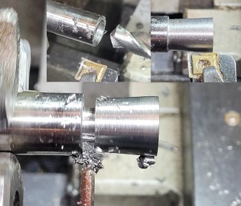
The parted surface of the ferrule was cleaned up with a belt sander using a scrap handle as the holding fixture. Then back to the lathe on a 15/32” diameter arbor, secured with a turned down flat head cap screw. Ran the lathe in reverse and used a corner-radius end mill to cut the radius in at the blade end of the ferrule. Then over to a Scotchbrite wheel using a scrap handle as the holding fixture to polish the ferrules.
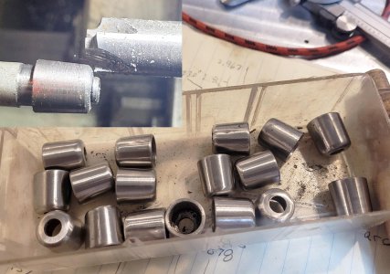
As an aside, the original ferrules also have a 3-degree taper on the inside. That’s so the handle end squeezes down on the tool shank as the ferrule is pounded down on the handle. My plan was to epoxy the ferrule/shank in place, so I didn’t taper the inside of the ferrule.
The slotted screwdriver shanks were made from 3/16” diameter 303 stainless steel. Blanks were cut to 5” long, and one end knurled to aid in handle-retention. I didn’t show the operation, but the blade ends were forged on an anvil and ground to shape with a bench grinder. Then over to a bench grinder with a Scotchbrite wheel for polishing.
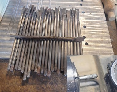
Final assembly goes pretty quickly. First, stage the screwdriver shanks with a ferrule slipped in place. Mix up some 5-minute epoxy, dip the knurled end of the shank into the glue, set the knurled end at the handle hole and tap down with a leather hammer. Then, flip the handle and feed the screwdriver shank through a bench block so the ferrule is setting on the block, and tap the ferrule home with a leather hammer on the end of the handle.
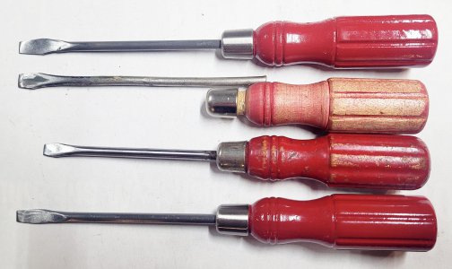
My reproductions at the top/bottom, originals in the middle. The original with a shank in place is too short, the shank should extend about 4" (repros are correct).
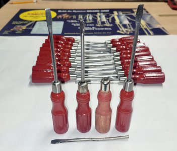
My first run was 20+ parts; I’m at 3 completed screwdrivers per hour. Wish me luck on eBay!
Thanks for looking, Bruce
The A.C. Gilbert Company was known for Erector sets and American Flyer trains. They also produced other toys like microscopes, Anchor blocks, chemistry sets, telescopes, puzzles, magic kits and carpentry sets. Gilbert was a master at “cross-pollenating” parts across their toy lines. For example, the caps used to secure the brushes on their small electric motors were also used as decorative tips on the magic wands in their magic sets.
Gilbert numbered Erector sets by size; bigger the number, the larger the set. In 1928, the largest set was a No. 10 and included one of the carpentry set slotted screwdrivers. The screwdriver was designated part# ‘B2’. The No. 10 sets included one of the ‘B2’ screwdrivers up through 1933. In 1931, Gilbert introduced the Erector Hudson locomotive and tender model and included a ‘B2’ in those sets up through 1934, maybe 1935.
1930 No. 10 Erector set; you can see the B2 screwdriver in the bottom layer near the top.


1931 No. 8 Hudson Locomotive Erector set, B2 is visible near the middle of the wooden box.

A lot of these sets are missing their ‘B2’ screwdriver. Probably because it was a handy size and was used for other jobs around the house.
There is actually a market for these. I’ve seen originals go for over $150 on eBay! Gilbert used the same wooden handle across the various tools included in their carpentry sets; a common practice is to pull the chisel blade, spokeshave, awl, etc. tool and replace it with a slotted screwdriver blade. These reproductions occasionally show up on eBay and bring around $80. The problem with those repros is the handle supply; you have to find a nearly 100-year-old tool set to make the reproduction ‘B2’. I made these repros from the ground up; better “business plan” as there are no supply issues for any of the components. I made the wooden handles from 1” birch dowels, ferrule from 303 stainless and the screwdriver blades from 3/16” 303. I’ll first go over the handle.
The handle has some shape to it and 8 flutes on the handle. My first thought was to make them on my Tormach 1100 mill which has a 4th axis. Chuck up a dowel between centers, cut the flutes with a ball-end mill indexing after each pass. Then change tools to a ¼” ball end mill to do the majority of the shaping; rotate the dowel with the 4th axis as the end mill burrows away. Then some finer grooving with an engraving bit. Though this process would let me start the cycle and walk away, I went the manual route (for now).
I ended up making a scraping tool from some 3/8” thick O-1 tool steel for the majority of the shaping. Started by milling a rake angle on the top, Dykem’d the top surface and scribed the two radii. Rough cut on the Bridgeport, then belt sanded & die filed to the scribe lines. Set the scraping tool to an original handle to verify the shape. I didn’t show it, but ground in a front relief angle with a die grinder and belt sander. The handle has a couple of grooves for “styling”; I marked their position on the scraping tool and center punched a line. Photos of this stuff are below.
Handle process was to first route the flutes into 3’ long dowels, cut them to length, and do the lathe work holding the dowel with a 5-C collet. Flute-indexing was done with an indexing plug that screws to the end of the dowel from 3/4" aluminum; the groove is only 0.030" deep so no fear of the router bit hitting the plug. The indexing plug had a shoulder a touch over 1/2" long turned to 5/8" diameter. Then to the Bridgeport and a dividing head to countersink 8 holes on 45 degree spacing and scribe a tick mark on the indexing plug. I used a mill/drill bit for that work.

Mounted the indexing plug vertically on the BP, found center with an SDA laser center finder, and drilled a couple of holes for finish nails. In use, the plan was to chuck up the dowel on the lathe, center drill and drill a hole for a deck screw which would lock the indexing plug to the dowel. The finish nails dig into the dowel and help the indexing plug from slipping.

Made a indexing collar that the indexing plug shown above slips into. Drilled and tapped a hole in the side for a cap screw with a pointed tip that slips into the countersunk holes in the indexing plug.

I didn't show the table saw/joiner work, but cut a little over 1" wide dado a little shy of 1" deep in the center of a 3x3. I went a little shy on the depth to ensure the dowel was slightly proud of the bottom of the 3x3. My worry was if a dowel had a little warp in it, the bit wouldn't cut to a uniform depth. Screwed the indexing plug to a dowel, slipped over the indexing collar, and set the assembly in the 3x3 for alignment before drilling the pilot holes and screwing the indexing collar in place. And some of the dowels were slightly warped; a "frown" shape resulted in a shallow cut in the middle. Easy fix was a second pass pushing down on the 3x3 to flatten the dowel.

I didn't have a 1/8" ball-end router bit, so made an arbor on the lathe for a 1/8" end mill. Mounted that in a router, adjusted the bit height

Fluting process was to screw the indexing plug to the end of a center-drilled dowel, set the dowel in the 3x3 and lock the plug in place with the cap screw in the collar. Make a pass on the router table, loosen the cap screw, rotate to the next mark, tighten the lock screw and repeat.

Once the flutes were in, the dowel was cut into individuals. Once on the lathe, center drilled, shank drilled and mounted between centers. Used the forming tool to scrape the shape into the dowel, pencil-transferred the groove positions, cut the grooves with a sharp threading tool, relieved the transition between the flutes and handle radii with a parting tool, filed in radii at the grooves/flutes, and sanded with 180-grit paper. Flipped the handle and worked a radius into the butt-end with a file/sanding block.
Scraping tool; rake angle cut on the BP, Dykem layout work, roughed on the BP, sanded/die filed to the scribed line and spot checked against an original handle.

Dowel blank being scraped to shape. The handle has a couple of decorative beads; scraping tool has those locations center punched for easy pencil-line transferring.

Cut the two grooves, then a flat at the flutes/radius, flipped the handle for facing and adding a radius to the end. The red handle is an original, bare one is my prototype.

I didn’t show it, but did some clean-up on the flutes at the bench. The ends of the flutes had a little tear-out from cutting in the radii which were cleaned up with a needle file mounted in a cordless drill. Dunked the handles in sanding sealer, scuffed with a Scotchbrite pad and rattle-can painted with 3 coats of Rustoleum Regal Red.

Next up are the ferrules. The original ferrules were made from CRS in a draw die and nickel-plated. The OD at the widest area is about 0.605”, 3-degree taper per side, overall length of ~0.630 and a wall thickness of ~0.0625”. Instead of a draw die (maybe a future POTD), I cut these from a piece of 303 stainless steel 5/8” diameter rod stock. Polished stainless steel is a nice substitute for nickel-plated CRS.
Started by center drilling and drilling a ¼” hole ¾” deep. Then drilled a 15/32” hole ½” deep; this is the back side hole of the ferrule that slips over the handle. Used a parting tool to mark the overall length of the part, then cut the outside surface 3-degree taper. After tapering, cleaned up the surface with a flat file, and parted to length.

The parted surface of the ferrule was cleaned up with a belt sander using a scrap handle as the holding fixture. Then back to the lathe on a 15/32” diameter arbor, secured with a turned down flat head cap screw. Ran the lathe in reverse and used a corner-radius end mill to cut the radius in at the blade end of the ferrule. Then over to a Scotchbrite wheel using a scrap handle as the holding fixture to polish the ferrules.

As an aside, the original ferrules also have a 3-degree taper on the inside. That’s so the handle end squeezes down on the tool shank as the ferrule is pounded down on the handle. My plan was to epoxy the ferrule/shank in place, so I didn’t taper the inside of the ferrule.
The slotted screwdriver shanks were made from 3/16” diameter 303 stainless steel. Blanks were cut to 5” long, and one end knurled to aid in handle-retention. I didn’t show the operation, but the blade ends were forged on an anvil and ground to shape with a bench grinder. Then over to a bench grinder with a Scotchbrite wheel for polishing.

Final assembly goes pretty quickly. First, stage the screwdriver shanks with a ferrule slipped in place. Mix up some 5-minute epoxy, dip the knurled end of the shank into the glue, set the knurled end at the handle hole and tap down with a leather hammer. Then, flip the handle and feed the screwdriver shank through a bench block so the ferrule is setting on the block, and tap the ferrule home with a leather hammer on the end of the handle.
My reproductions at the top/bottom, originals in the middle. The original with a shank in place is too short, the shank should extend about 4" (repros are correct).


My first run was 20+ parts; I’m at 3 completed screwdrivers per hour. Wish me luck on eBay!
Thanks for looking, Bruce


 That's okay, you do better work and you are honest about it.