- Joined
- Feb 5, 2015
- Messages
- 662
As usual, I wondered about the best sub-forum to post this. I made an assumption that this one was often read by members of various experience so here's my (brief) experience with the shearing tool.
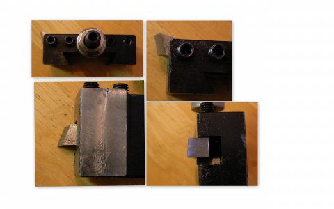
I’ve read about the magical shearing tool for some years. Considering the various sources, it seemed that the advantages might be offset by the disadvantages. A while ago. I conducted a very brief experiment to try and confirm/disprove points that I’ve read:
Advantages
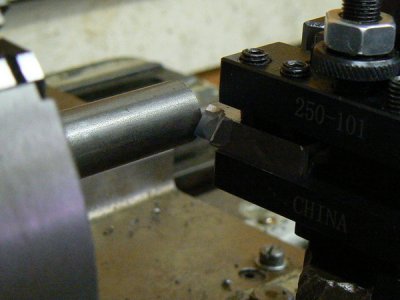
The initial experiments were impressive. I was able to achieve better finishes on hard to machine material than I’d been able to obtain previously. Not only that, but accuracies were also better than those achieved in normal practice, within some limitations discussed later.
Angling the Compound
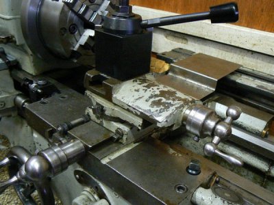
A common practice (when workpiece configuration permits) for precision work, is to use the compound, rather than the cross slide, for cutting tool depth adjustment. The compound angle is usually adjusted to 5.7 degrees from the lathe spindle centerline. (Six degrees will work just fine, LOL.)
This angle provides a 10:1 slope of compound “X” movement to “Y” movement. So a compound movement of .001 results in a movement toward the spindle (the “Y” axis) of .0001. Of course this presumes that the cross slide lead screw is accurate in both lead and wear. That’s not necessarily a valid presumption for old machinery.
First Cutting Trial
As noted initially, one of the advantages of the shear tool is that angles are mostly uncritical. In fact only one angle, the face of the tool requires re-sharpening.
I chose to orient the shearing tool roughly along the spindle axis rather than in the cross slide axis as others have done. Back clearance for the cutting tool is easily obtained by simply angling the cutter slightly in the tool holder. Either orientation works fine.
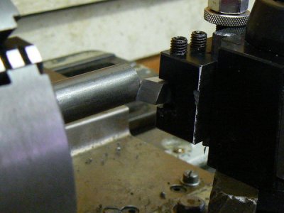
One of the first things one observes when using this tool is the chips that result from the cutting process. Well, not really chips, more like the finest steel wool that you’ve ever seen. Recalling that best results for this tool suggest a DOC to be less than .002, I don’t know why I was surprised by this.
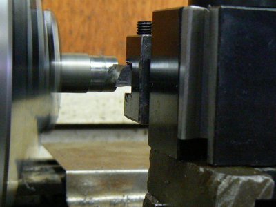
You have to look carefully at the following photo to see the chips – they are mixed with cutting oil and sort of piled up just in front of the cutting tool and around the workpiece.
Here’s a photo of some 1018 material after turning with a sharp, conventional cutting tool, depicting the typical crappy surface finish that is typical of this material.
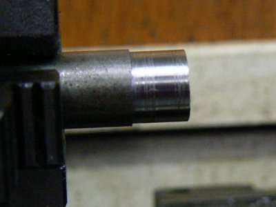
And this is the same workpiece after taking a .001 finishing pass with the shearing tool. Note that the surface finish almost looks like it’s been ground. Five seconds time with some 0000 steel wool would have really polished it up !
Evaluating Accuracy
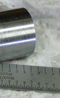
OK, the next exercise was to determine if, as claimed, the shearing tool was able to provide “tenths” precision. First, measuring the diameter after the initial shearing cut, I obtained a figure of .6903. I wanted to turn the diameter to .6900 within .0001 at shop temperature (more on this later).
Recalling that there is a 10:1 “Y” axis advantage when the cross-slide is adjusted to about 6 degrees but also recalling that we need move the cutting tool only half of the difference to reduce the diameter by a factor of 2. So the compound is carefully adjusted by moving it toward the workpiece 1 division.
After turning the workpiece to the new adjustment, the measured diameter is now .6902. The diameter was NOT reduced by .0002 as it should have been. This is not surprising given that the lathe is 70 years old.
A Brief Interruption To Discuss Temperature Effects On Accuracy
This is a good time to point out that “tenths accuracy” is likely a transient condition, depending on the material, the size of the work and the temperature – especially the temperature. It’s possible for material being rough-turned in a lathe to heat as much as 30 degrees Centigrade. Approximate coefficients of linear thermal expansion for some common materials are as follows:
Let’s estimate a hypothetical example:
After rough-turning to within .002 inches of finish diameter, a 2.5 inch diameter aluminum workpiece is to be finish-turned with a shearing tool to 2.4980 inches with a tolerance of +/- .0002 inches.
The rough-turning operation is presumed to have raised the workpiece temperature 13 degrees C but the shear turning operation (removing very little material) is assumed to have resulted in the work cooling (air cooling from spindle rotation) a couple of degrees.
How much does the finish diameter vary when the workpiece cools the final 11 degrees to normal shop temperature ? The shrinkage due to cooling is: Temperature coefficient of expansion x work diameter x temperature difference and using the actual figures:
.000007 x 2.4980 x 11 = .0002 inches
So the desired .0002 tolerance has been exceeded in just 11 degrees of temperature variation. One must always be conscious of temperature effects when making precision parts, most especially when the parts are of dissimilar materials.
If mating parts are similar materials, for example a steel shaft mating with a steel ball bearing, then temperature variation is less important but still must be considered. When the steel shaft is turned for a precision fit with the bearing it first should be allowed to come to the same temperature as the bearing.
If that is confusing, I’m presuming that the shaft fit has been determined by the measured I.D. of the bearing. So common sense suggests that the shaft should be finish turned at the same temperature the bearing was measured. Please note that dimensional variation is also directly dependant on part size so small parts may not be as temperature-critical.
In my original description, one of the disadvantages of this tool is that very fine DOC and very fine feeds are suggested for best results. The obvious implication is that, if one is pressed for time, this is probably not the technique for you. If better precision is required than a standard cutting tool can provide, maybe a file and some sandpaper could be better options.
Clearly, one should use standard techniques to get within .003 or so, leaving enough stock to achieve finish diameter in two passes. Why two passes ? Because measuring the result of the first pass will tell you if moving the compound is really providing a 10:1 movement. If not, you can adjust for that in the second, finishing pass.
Returning To The Current Example
Returning to the .6902 diameter just turned with the shear tool, I adjusted the compound another full division toward the work … the .001 graduation on the compound should equal .0001 tool movement because of the 10:1 advantage of the 6 degree offset compound. This should result in a reduction of the workpiece diameter of .0002.
After making the finish cut with the shearing tool, success ! The finish diameter is .6900 at shop temperature according to my one inch vernier micrometer.
I attempted to photograph the micrometer when measuring diameters but no useful photos could be obtained. The photos couldn’t accurately show the vernier alignments that are necessary to determine .0001 graduations. You’ll have to take my measurements on faith or, better still, make a shearing tool, re-align your compound and make your own evaluation.
Taper ?
I didn’t attempt to turn a very long piece of work to determine if there was taper. There are several reasons but one is that the shallow DOC, very fine feed and relatively slow spindle RPM makes any experiment with this tool time-consuming.
Additionally, I didn’t want the wear of my old Sheldon lathe to add error that was not caused by tool wear. I did turn a short length of 1018 (about 3 inches) and noted a taper of about .0003 using the HSS shear tool shown in the second photo at the beginning of this post.
Although it wouldn’t be my first choice for this type of tool, I mounted a brazed-carbide AL lathe tool sideways in a tool holder. This was an approximation of normal shearing tool configuration. Turning the same workpiece with a DOC approximately .0003 resulted in taper less than .0001.
I make no conclusions about the taper experiment, I’m just presenting observations made on a sample of one. The machine is well-worn and there could be any number of explanations for an improvement in the taper. (Not to mention the fact that measurements in the .0001 range, using average measuring tools may produce inconsistent results.)
Preliminary Conclusions
If the amount of time to turn a precision surface is not considered, I believe that the initial experiment was successful based on the following:
I’ve read about the magical shearing tool for some years. Considering the various sources, it seemed that the advantages might be offset by the disadvantages. A while ago. I conducted a very brief experiment to try and confirm/disprove points that I’ve read:
Advantages
- Fine surface finish
- Ability to achieve very close tolerances
- Geometry is not critical
- Because of less cutting deflection (from the smaller DOC) possibility of turning longer workpieces, without support from a center or steady, compared to a conventional cutting tool
- Depth of cut about .002 max for HSS cutter without excessive cutting edge wear
- Best results suggest very fine feed (IPR) and slow RPM requiring a LOT of time
- Carbide cutter may not be practical due to the need of a very sharp edge
- Cutting tool may wear quickly due to near "point contact" – possibly quickly enough to turn a measurable taper during a long cut

The initial experiments were impressive. I was able to achieve better finishes on hard to machine material than I’d been able to obtain previously. Not only that, but accuracies were also better than those achieved in normal practice, within some limitations discussed later.
Angling the Compound
A common practice (when workpiece configuration permits) for precision work, is to use the compound, rather than the cross slide, for cutting tool depth adjustment. The compound angle is usually adjusted to 5.7 degrees from the lathe spindle centerline. (Six degrees will work just fine, LOL.)
This angle provides a 10:1 slope of compound “X” movement to “Y” movement. So a compound movement of .001 results in a movement toward the spindle (the “Y” axis) of .0001. Of course this presumes that the cross slide lead screw is accurate in both lead and wear. That’s not necessarily a valid presumption for old machinery.

First Cutting Trial
As noted initially, one of the advantages of the shear tool is that angles are mostly uncritical. In fact only one angle, the face of the tool requires re-sharpening.
I chose to orient the shearing tool roughly along the spindle axis rather than in the cross slide axis as others have done. Back clearance for the cutting tool is easily obtained by simply angling the cutter slightly in the tool holder. Either orientation works fine.

One of the first things one observes when using this tool is the chips that result from the cutting process. Well, not really chips, more like the finest steel wool that you’ve ever seen. Recalling that best results for this tool suggest a DOC to be less than .002, I don’t know why I was surprised by this.
You have to look carefully at the following photo to see the chips – they are mixed with cutting oil and sort of piled up just in front of the cutting tool and around the workpiece.

Here’s a photo of some 1018 material after turning with a sharp, conventional cutting tool, depicting the typical crappy surface finish that is typical of this material.

And this is the same workpiece after taking a .001 finishing pass with the shearing tool. Note that the surface finish almost looks like it’s been ground. Five seconds time with some 0000 steel wool would have really polished it up !

Evaluating Accuracy
OK, the next exercise was to determine if, as claimed, the shearing tool was able to provide “tenths” precision. First, measuring the diameter after the initial shearing cut, I obtained a figure of .6903. I wanted to turn the diameter to .6900 within .0001 at shop temperature (more on this later).
Recalling that there is a 10:1 “Y” axis advantage when the cross-slide is adjusted to about 6 degrees but also recalling that we need move the cutting tool only half of the difference to reduce the diameter by a factor of 2. So the compound is carefully adjusted by moving it toward the workpiece 1 division.
After turning the workpiece to the new adjustment, the measured diameter is now .6902. The diameter was NOT reduced by .0002 as it should have been. This is not surprising given that the lathe is 70 years old.
A Brief Interruption To Discuss Temperature Effects On Accuracy
This is a good time to point out that “tenths accuracy” is likely a transient condition, depending on the material, the size of the work and the temperature – especially the temperature. It’s possible for material being rough-turned in a lathe to heat as much as 30 degrees Centigrade. Approximate coefficients of linear thermal expansion for some common materials are as follows:
- Aluminum, 7 ppm/inch/inch/deg C
- Brass, 6 ppm/inch/inch/deg C
- Stainless steel, 5 ppm/inch/inch/deg C
- Carbon steel, 4 ppm/inch/inch/inch/deg C
Let’s estimate a hypothetical example:
After rough-turning to within .002 inches of finish diameter, a 2.5 inch diameter aluminum workpiece is to be finish-turned with a shearing tool to 2.4980 inches with a tolerance of +/- .0002 inches.
The rough-turning operation is presumed to have raised the workpiece temperature 13 degrees C but the shear turning operation (removing very little material) is assumed to have resulted in the work cooling (air cooling from spindle rotation) a couple of degrees.
How much does the finish diameter vary when the workpiece cools the final 11 degrees to normal shop temperature ? The shrinkage due to cooling is: Temperature coefficient of expansion x work diameter x temperature difference and using the actual figures:
.000007 x 2.4980 x 11 = .0002 inches
So the desired .0002 tolerance has been exceeded in just 11 degrees of temperature variation. One must always be conscious of temperature effects when making precision parts, most especially when the parts are of dissimilar materials.
If mating parts are similar materials, for example a steel shaft mating with a steel ball bearing, then temperature variation is less important but still must be considered. When the steel shaft is turned for a precision fit with the bearing it first should be allowed to come to the same temperature as the bearing.
If that is confusing, I’m presuming that the shaft fit has been determined by the measured I.D. of the bearing. So common sense suggests that the shaft should be finish turned at the same temperature the bearing was measured. Please note that dimensional variation is also directly dependant on part size so small parts may not be as temperature-critical.
In my original description, one of the disadvantages of this tool is that very fine DOC and very fine feeds are suggested for best results. The obvious implication is that, if one is pressed for time, this is probably not the technique for you. If better precision is required than a standard cutting tool can provide, maybe a file and some sandpaper could be better options.
Clearly, one should use standard techniques to get within .003 or so, leaving enough stock to achieve finish diameter in two passes. Why two passes ? Because measuring the result of the first pass will tell you if moving the compound is really providing a 10:1 movement. If not, you can adjust for that in the second, finishing pass.
Returning To The Current Example
Returning to the .6902 diameter just turned with the shear tool, I adjusted the compound another full division toward the work … the .001 graduation on the compound should equal .0001 tool movement because of the 10:1 advantage of the 6 degree offset compound. This should result in a reduction of the workpiece diameter of .0002.
After making the finish cut with the shearing tool, success ! The finish diameter is .6900 at shop temperature according to my one inch vernier micrometer.
I attempted to photograph the micrometer when measuring diameters but no useful photos could be obtained. The photos couldn’t accurately show the vernier alignments that are necessary to determine .0001 graduations. You’ll have to take my measurements on faith or, better still, make a shearing tool, re-align your compound and make your own evaluation.
Taper ?
I didn’t attempt to turn a very long piece of work to determine if there was taper. There are several reasons but one is that the shallow DOC, very fine feed and relatively slow spindle RPM makes any experiment with this tool time-consuming.
Additionally, I didn’t want the wear of my old Sheldon lathe to add error that was not caused by tool wear. I did turn a short length of 1018 (about 3 inches) and noted a taper of about .0003 using the HSS shear tool shown in the second photo at the beginning of this post.
Although it wouldn’t be my first choice for this type of tool, I mounted a brazed-carbide AL lathe tool sideways in a tool holder. This was an approximation of normal shearing tool configuration. Turning the same workpiece with a DOC approximately .0003 resulted in taper less than .0001.
I make no conclusions about the taper experiment, I’m just presenting observations made on a sample of one. The machine is well-worn and there could be any number of explanations for an improvement in the taper. (Not to mention the fact that measurements in the .0001 range, using average measuring tools may produce inconsistent results.)
Preliminary Conclusions
If the amount of time to turn a precision surface is not considered, I believe that the initial experiment was successful based on the following:
- Surface finish of the 1018 workpiece was dramatically improved with the shear tool
- The shear tool (combined with angular offset of the compound) can produce accuracies in the .0001 range with careful procedure because it has the ability to remove very small amounts of material without deflecting the work excessively
- A longitudinally-mounted shear tool (roughly parallel with the spindle axis) is very easy to sharpen and maintain since only one face is ground
- Centering the cutting tool with the workpiece axis is uncritical because the cutting edge of the shear tool can cut along its entire edge
- Exposing a new, sharp edge of the shear tool is as simple as moving it up or down in the tool holder


