- Joined
- Jan 24, 2015
- Messages
- 239
Dear All,
It has been too long since I visited! So, I have decided to post a POTD. I am just starting to build Elmer's Grasshopper beam steam engine model. The first task I tried was the flywheel. I changed the plans a bit, as I decided to go with a 3.5" flywheel instead of the 3" flywheel the drawings call for. More mass should make for a better grass...hopper.
I had previously made the flywheel blank. It is 3.5" in diameter, 7/16" thick, with a .400 wide rim and a 3/4" tapered hub. The spoke area is recessed to make the web 1/8" thick.
The project was to cut the spokes.
The flywheel has six tapered spokes. With my rotary table and DRO, straight spokes are pretty easy, but the math for getting a tapered spoke was escaping me. So I found this document, which helped a ton. His whole website is full of useful info. Even with the help, most of the shop time was doing the math and checking it twice. I then did a few test cuts on some cereal box cardboard.
Anhoo, here are some photos:
Drilled holes in the vertices of the spokes. The 12 outer holes are 3/16", the six inner holes are 1/4".
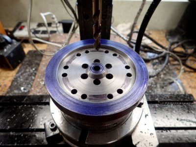
The rim cuts were then made with a 3/16 2-flute HSS endmill turning at 2100 rpm.
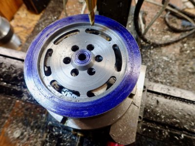
The RT was moved in the X and Y for cutter offsets and the angle of spoke taper (2.6 degrees) was dialed in. Then the first side of each spoke was cut, advancing 60 degrees each time. Same end mill, same speed.
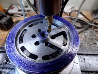
The other side was cut, again moving the in the X and Y for the offset, and going to -2.6 degrees for the taper.
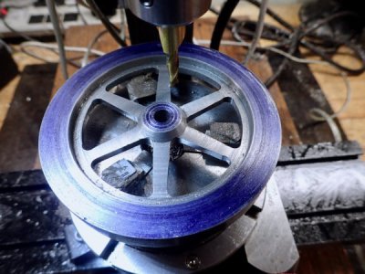
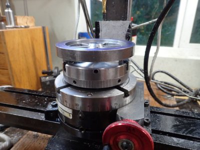
Here is the RT set up. 3.5" RT with a 3" 3-jaw chuck. The flywheel is sitting on cereal box cardboard bits so I don't chew up the chuck jaws.
Flywheel de-burred:
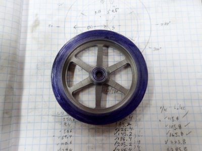
Then I used my dremel and a diamond drum bit to round over the edges, followed by some hand filling. I still have some filing and sanding to do.
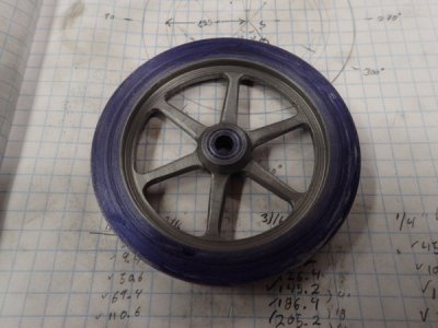
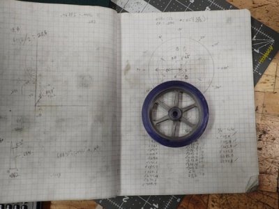
Here is a shot a the end, showing some of the math. I was always terrible at showing my work in math class.
Thanks for following along!
Tom
It has been too long since I visited! So, I have decided to post a POTD. I am just starting to build Elmer's Grasshopper beam steam engine model. The first task I tried was the flywheel. I changed the plans a bit, as I decided to go with a 3.5" flywheel instead of the 3" flywheel the drawings call for. More mass should make for a better grass...hopper.
I had previously made the flywheel blank. It is 3.5" in diameter, 7/16" thick, with a .400 wide rim and a 3/4" tapered hub. The spoke area is recessed to make the web 1/8" thick.
The project was to cut the spokes.
The flywheel has six tapered spokes. With my rotary table and DRO, straight spokes are pretty easy, but the math for getting a tapered spoke was escaping me. So I found this document, which helped a ton. His whole website is full of useful info. Even with the help, most of the shop time was doing the math and checking it twice. I then did a few test cuts on some cereal box cardboard.
Anhoo, here are some photos:
Drilled holes in the vertices of the spokes. The 12 outer holes are 3/16", the six inner holes are 1/4".

The rim cuts were then made with a 3/16 2-flute HSS endmill turning at 2100 rpm.

The RT was moved in the X and Y for cutter offsets and the angle of spoke taper (2.6 degrees) was dialed in. Then the first side of each spoke was cut, advancing 60 degrees each time. Same end mill, same speed.

The other side was cut, again moving the in the X and Y for the offset, and going to -2.6 degrees for the taper.

Here is the RT set up. 3.5" RT with a 3" 3-jaw chuck. The flywheel is sitting on cereal box cardboard bits so I don't chew up the chuck jaws.

Flywheel de-burred:

Then I used my dremel and a diamond drum bit to round over the edges, followed by some hand filling. I still have some filing and sanding to do.

Here is a shot a the end, showing some of the math. I was always terrible at showing my work in math class.

Thanks for following along!
Tom
