Frejoth FI-900 wiring diagram

Seems like there was an earlier question about the motor HP; it is one hp.
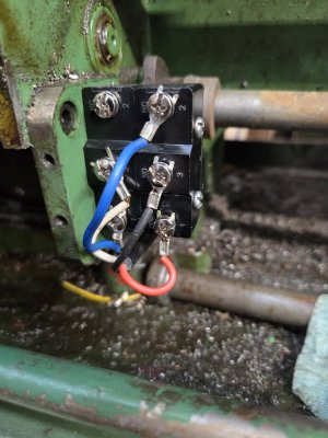
I lifted yellow wires 3-4-5 and the motor stopped. I checked for continuity between R3 and B4 also R3 and W5 (believing if there was a short between those it show as a completed circuit); there was no continuity.

The control box got damaged when my neighbor picked it up with forks and it went over backwards. When I looked a the lathe a few weeks prior, the motor only engaged with the power switch and pink jumper. That's what started this odyssey. And again, thanks for taking time to help a complete stranger with a bum lathe and a multimeter.
 
OK something is haunted with that terminal strip it seems. Maybe just the act of lifting those 3 wires did something.
The metal parts of the strip could be touching the box behind, from the damage.
Ultimately I think you'll need to replace that strip. For now you could just remove all the wires from those 3 positions and fasten them together with small hardware, then tape. Temporary fix. Ugly but functional. The contactors may not last long anyhow. Then you toss all that stuff and
put a drum switch. Keep the transformer it has resale value. They don't make those anymore and they are sought-after.

You did check the microswitch wiring matches the sketch I did? You can check the switch behavior with your meter also
while the 3 yellows are lifted. Red3 to blk4 should connect for jog or forward and red3 to wht5 should connect for reverse.
 
Last edited:
The three yellow wires are secured to their respective wires and taped. The black and white wires were reversed at the micro-switches so I moved them to their correct position. There is a blue jumper wire (looks factory) from the bottom of the forward switch to the top of the reverse switch that hasn't been mentioned. I'll post a picture. I removed it to see if it made any change and it did not. So the function is the same; no carriage control, only the power switch starts the motor.
 
Blue jumper wire pic
 

Attachments

  • 20240406_100033.jpg
    20240406_100033.jpg
    247.4 KB · Views: 9
I'll take another look- did you test the switches with the yellows lifted as in post 32?
 
That's weird.
Let's review:
1) Previously, when you turned on the power switch the motor would run (this is after we tied the two yellow panel wires together)
2) Then, you lifted the yellow terminal strip wires 3,4 and 5. Then motor stopped when power switch turned on.
3) You checked the microswitch wires and found an error or two, fixed those. The microswitch group seems to show proper continuity.
4) You reconnected the three wires from the microswitch group and... the motor runs when you turn on the power switch?

Not clear on that last one, but the only thing left is the cams. If they are set properly the switches should be open and there should
be no connection between the three wires red, black and white, with apron lever in neutral.
 
Last edited:
Yes, the motor runs with the power switch. In a previous test with yellow 3-4-5 removed, I had no continuity between R3, B4 or W5. Now with those three wires removed from the terminal block and joined together (Y3 to R3, Y4 to B4 and Y5 to W5) I do have continuity between R3 and B4 (with 80 ohms resistance) and R3 to W5 has continuity and no resistance. So at this point there is a connection between those three wires from the microswitch group. Forgive me if I have misunderstood something.
 
OK well then the simple answer is you need to check/adjust those cams for proper engagement- I've mentioned this I think
If you have already done that then I am at a loss to explain

Keep in mind that the forward microswitch of the pair may or may not be the rightmost one. It depends on the cam mechanism and design.
It could in fact be the leftmost one on this machine. If it's a single-piece cam then whichever switch actuates when you drop the apron lever is the forward one (on most machines)

Also, the normal forward/jog rotation for the spindle is counter-clockwise, when viewed from the tailstock end. Connecting the Red3 and Blk4 should give that direction. If it's opposite, the motor may actually be wired backwards; easy to correct.

Lastly, the 80 ohm reading sounds weird- an closed circuit should read close to 0.00. And an open circuit like 1999 or OL
A switch contaminated by liquid might read 80,000 ohms (80K), but not 80.
Ciao- I'll check back in a day or two
 
Last edited:
It works! The jog button was stuck in the on position and that's why the chuck rotated each time the power was turned on. I decided to go back through everything from the carriage switches on back and was still getting the weird readings. Since I had tried everything else I decided to remove the jog button from the equation. I checked continuity at those two wires and found the circuit closed, with no change when I pushed the button. When I turned the power on the motor did not turn so I checked the carriage controls and they work as they should.
I cannot thank you enough for sticking with this novice and patiently offering your advice and clear illustrations! You likely told me to remove the jog button wires way back and I overlooked that. Thanks again.
 
Back
Top