Hi all….this more like a Part 2 to my original post (Gear cutter Depth of cut)
I’m going to try to keep this short and still provide enough info to get some ideas or opinions.
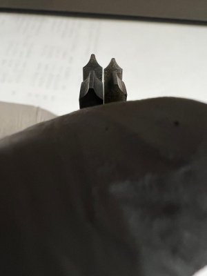
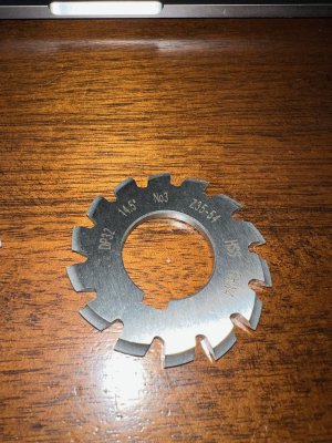
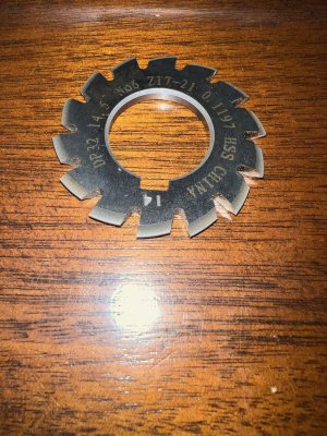
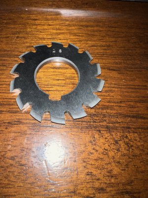
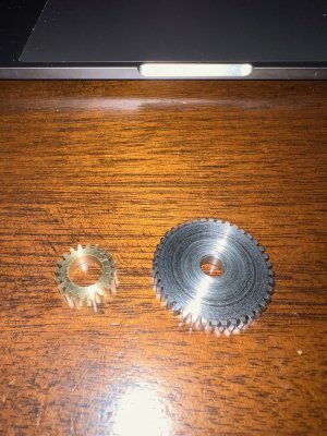
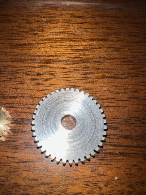
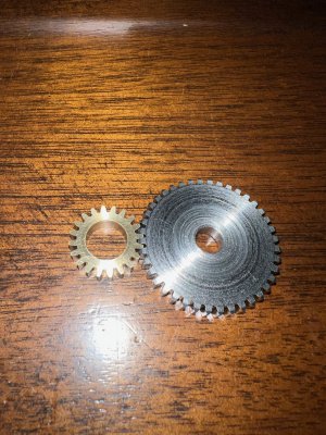
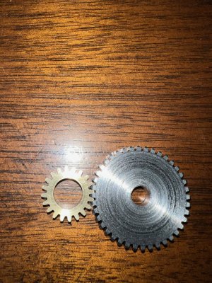
I bought two 32DP gear cutters..#3 and #6 to cut a 20 tooth and 40 tooth gear. Cutters are marked #3 Z35-54 and #6 Z17-21. I cut the 40 tooth gear with the #3 and it was spot on when measured across wires. I then cut the 20 tooth gear with the #6 and this is where things went wrong. I fed in .0674 and the teeth came to a point. Knowing that the numbering of the import cutters is suspect I cut a second 20 tooth gear with the #3 (feeding in the same .0674) and got a gear that looked right and also measured across pins within a 1/2 thou. I then cut another 40 tooth gear (feeding in the same .0674) with the #6, thinking the cutter numbers were wrong, and the teeth on this gear came to a point. So now I’m confused as hell. I’ve checked and re-checked my math and setup and am satisfied it’s good. I got my depth of cut of .0674 from 2.157/32. There are markings/numbers on the #6 cutter and a number which appears to be “26” stamped on one side of the #3 cutter. I’m sure those numbers mean something, but I can’t figure it out. I’ve tried working those numbers in the markings to see if they mean something in metric or imperial and can’t get anything that makes sense.
I have attached photos of the cutters (both sides), the cutter profiles, and the gears made. I’m hoping one the many experienced guys on here can help me out and point me in the right direction. Thanks
I’m going to try to keep this short and still provide enough info to get some ideas or opinions.
I bought two 32DP gear cutters..#3 and #6 to cut a 20 tooth and 40 tooth gear. Cutters are marked #3 Z35-54 and #6 Z17-21. I cut the 40 tooth gear with the #3 and it was spot on when measured across wires. I then cut the 20 tooth gear with the #6 and this is where things went wrong. I fed in .0674 and the teeth came to a point. Knowing that the numbering of the import cutters is suspect I cut a second 20 tooth gear with the #3 (feeding in the same .0674) and got a gear that looked right and also measured across pins within a 1/2 thou. I then cut another 40 tooth gear (feeding in the same .0674) with the #6, thinking the cutter numbers were wrong, and the teeth on this gear came to a point. So now I’m confused as hell. I’ve checked and re-checked my math and setup and am satisfied it’s good. I got my depth of cut of .0674 from 2.157/32. There are markings/numbers on the #6 cutter and a number which appears to be “26” stamped on one side of the #3 cutter. I’m sure those numbers mean something, but I can’t figure it out. I’ve tried working those numbers in the markings to see if they mean something in metric or imperial and can’t get anything that makes sense.
I have attached photos of the cutters (both sides), the cutter profiles, and the gears made. I’m hoping one the many experienced guys on here can help me out and point me in the right direction. Thanks