- Joined
- Jan 20, 2021
- Messages
- 296
Some trading with a buddy resulted in this guy coming home with me last summer..
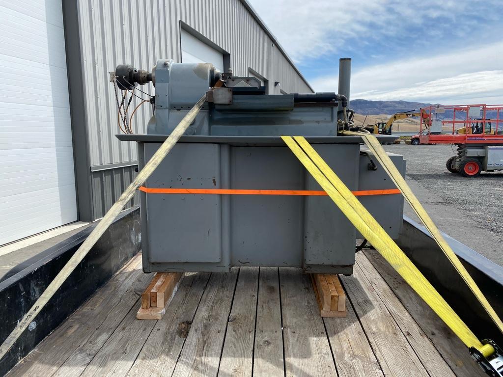
Before we loaded it on the trailer:
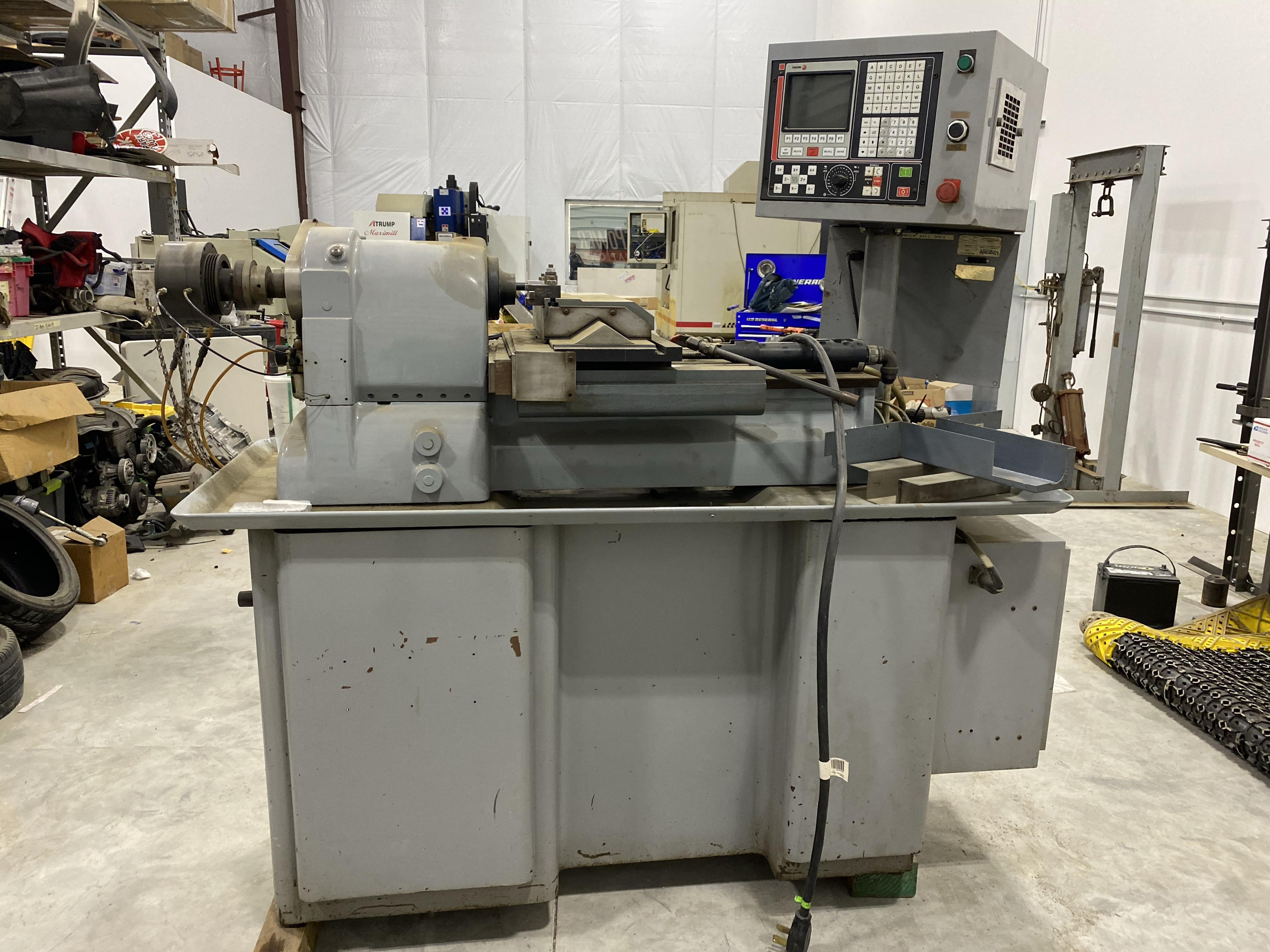
Hardinge lathe with Upgrade Technologies Accuslide CNC conversion with Fagor control. I will be installing new servos and Centroid control. Very similar to my mill conversion. Should make a really nice CNC lathe for my shop.
Got the lathe unloaded off the trailer and roughly in its resting place. It will stay on the cribbing until the controls are installed. Overall it’s in excellent condition. Was quite dirty. Still some cleaning left. Starting to sort out the existing control circuits. Most of the new control components are ordered. The existing Accuslide CNC conversion mechanical components look to be in great condition. I’ll have to source or make a few way cover parts that are missing. I have a 3 jaw chuck on the way.
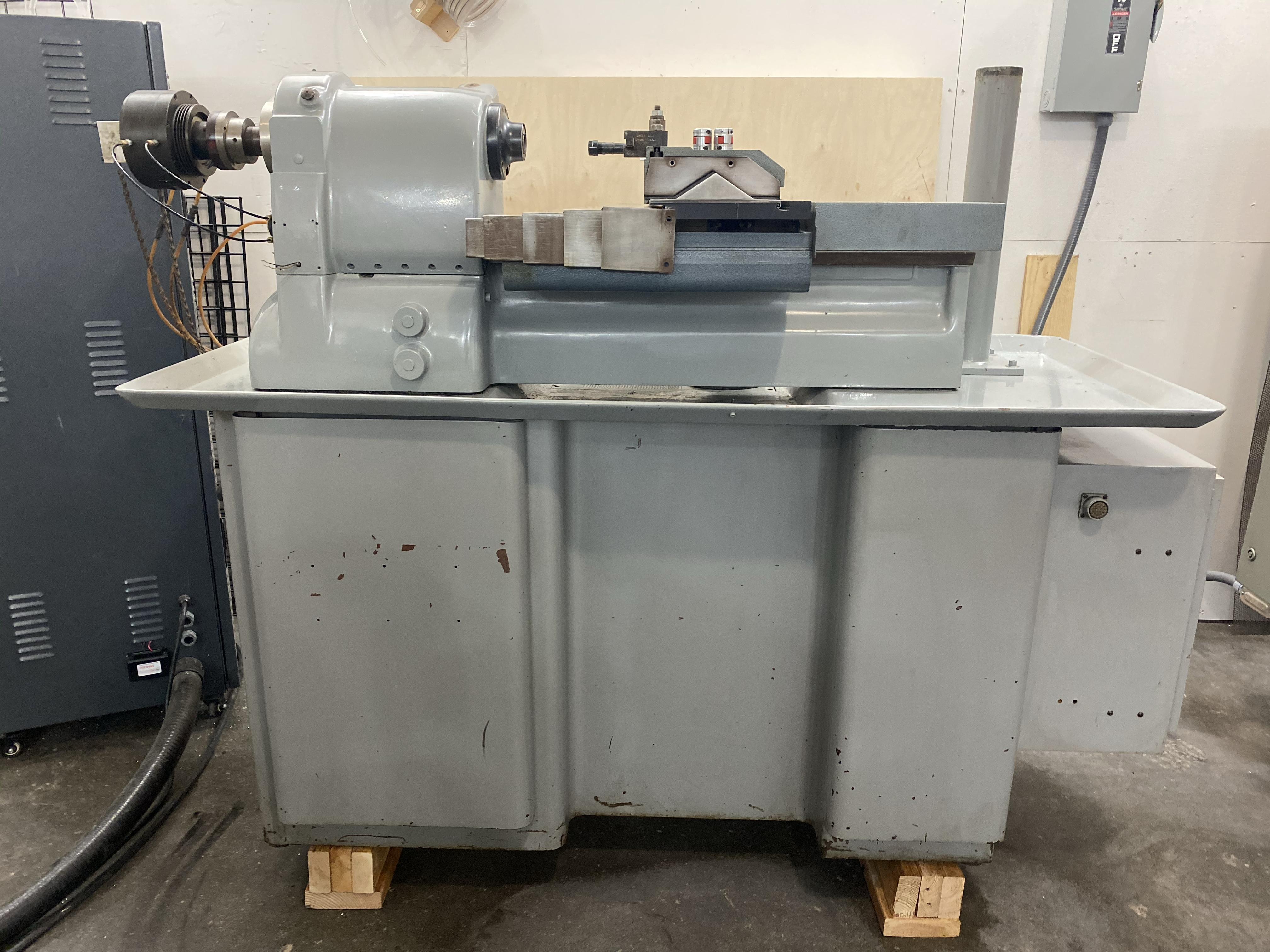
I sorted out how to move the Accuslide away from the spindle. This will allow me full use of the X axis travel.
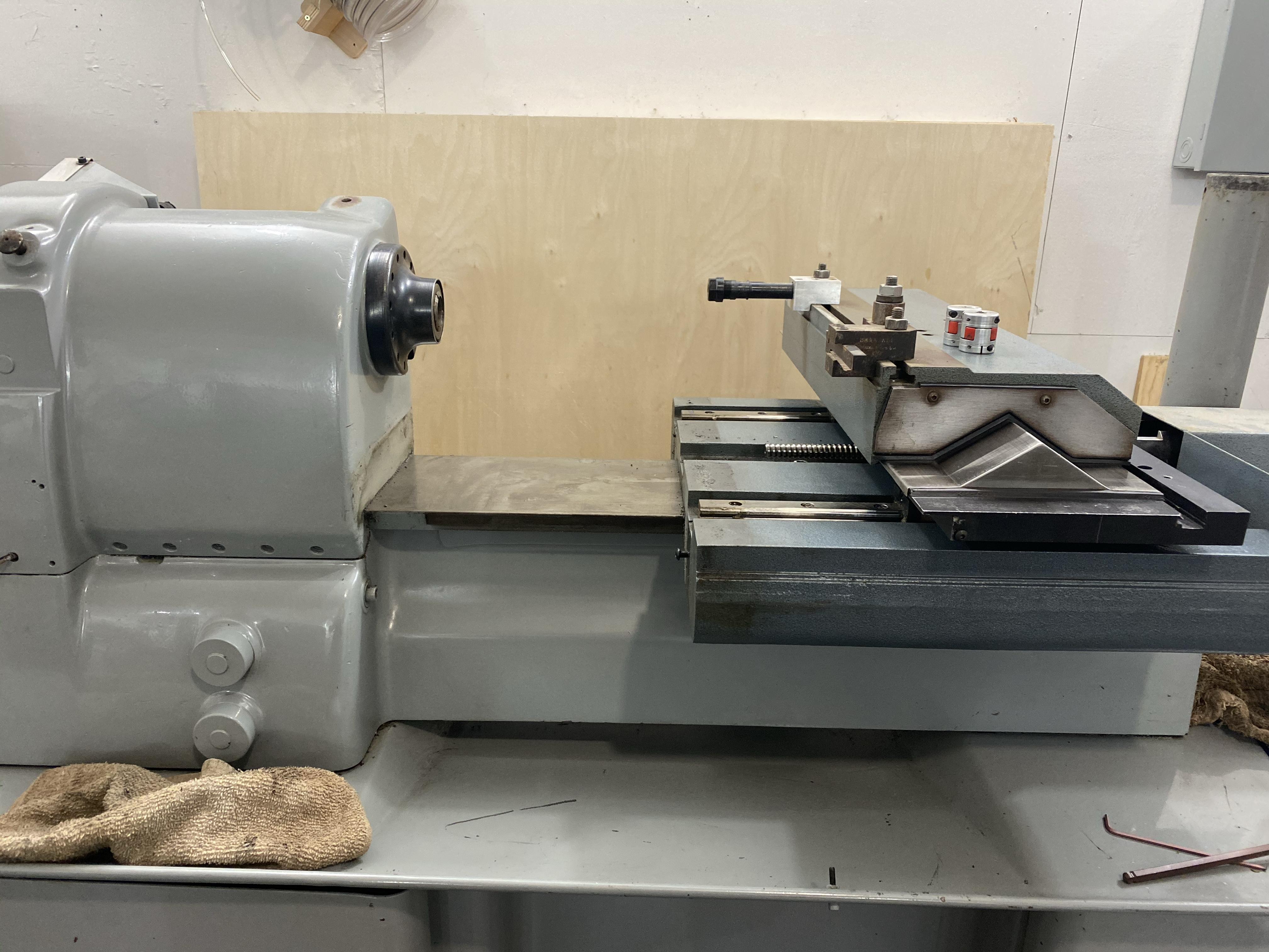
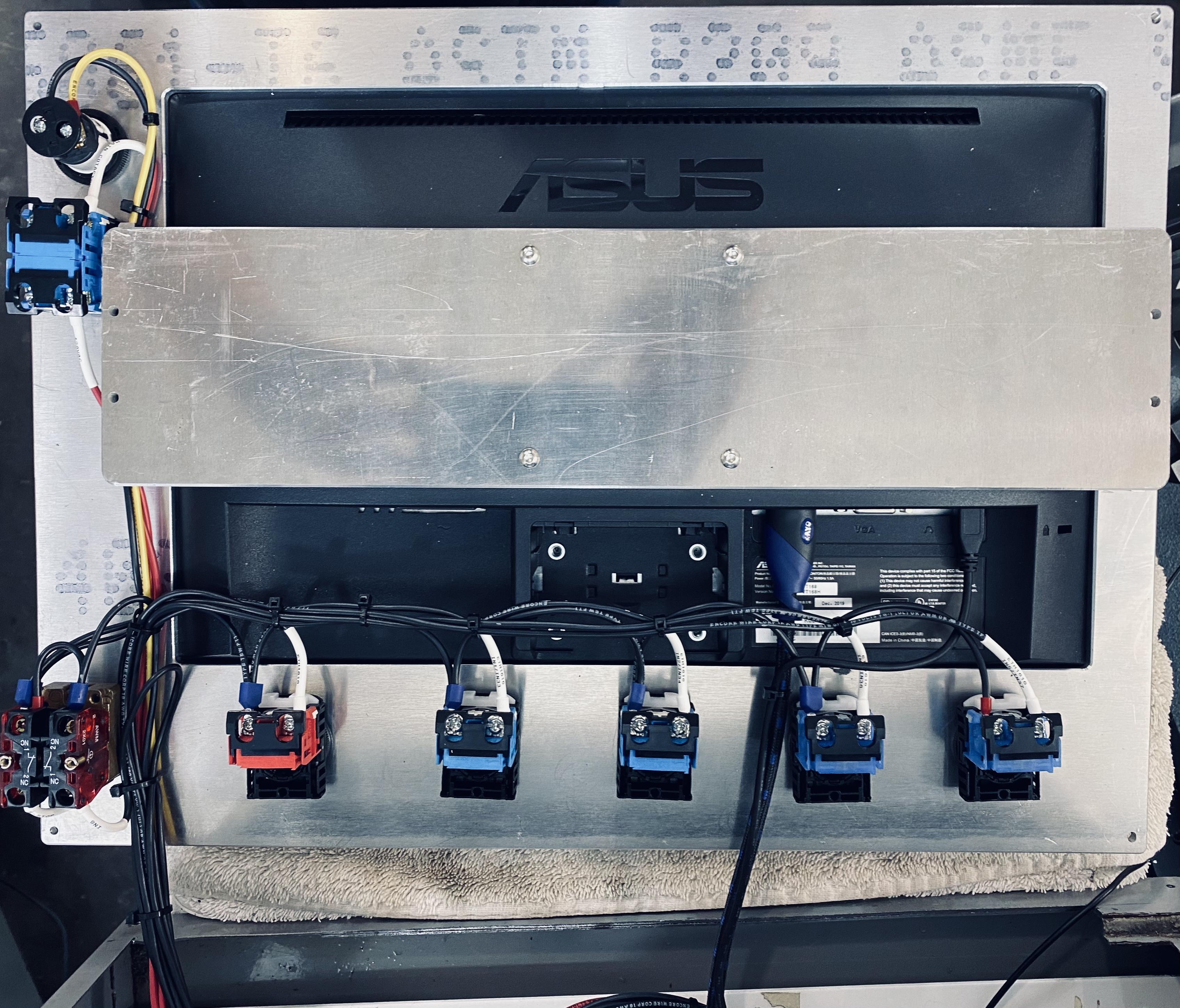
While waiting for parts to arrive, I made a mdf sample of the control panel layout. Test piece is made out of 1/8 mdf on the laser to check dimensions, layout, etc. I think this is what I’ll be going with.
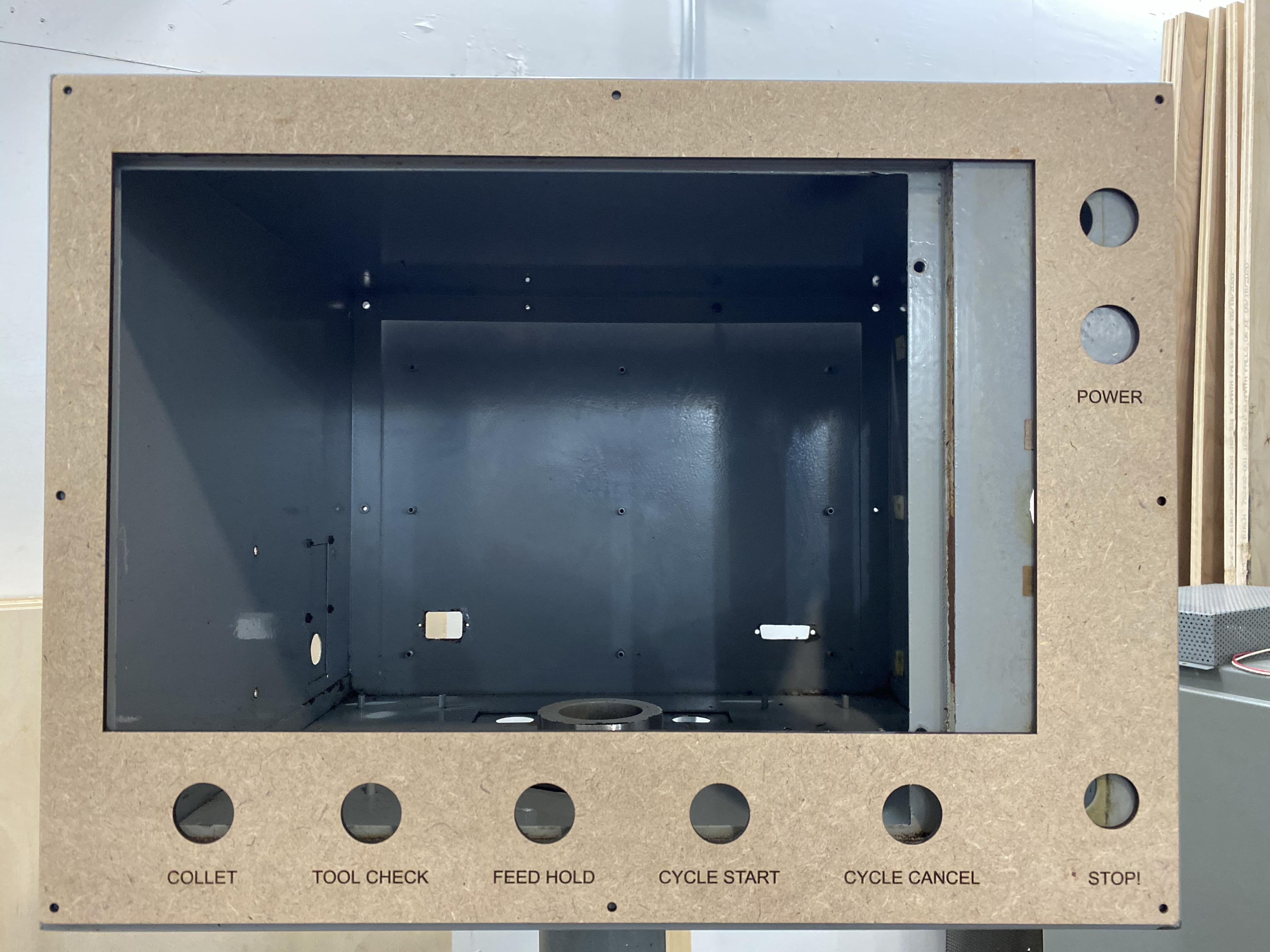
Touchscreen arrived. Got a great deal on Amazon Warehouse deals. Almost half price.
MDF mockup looks good.
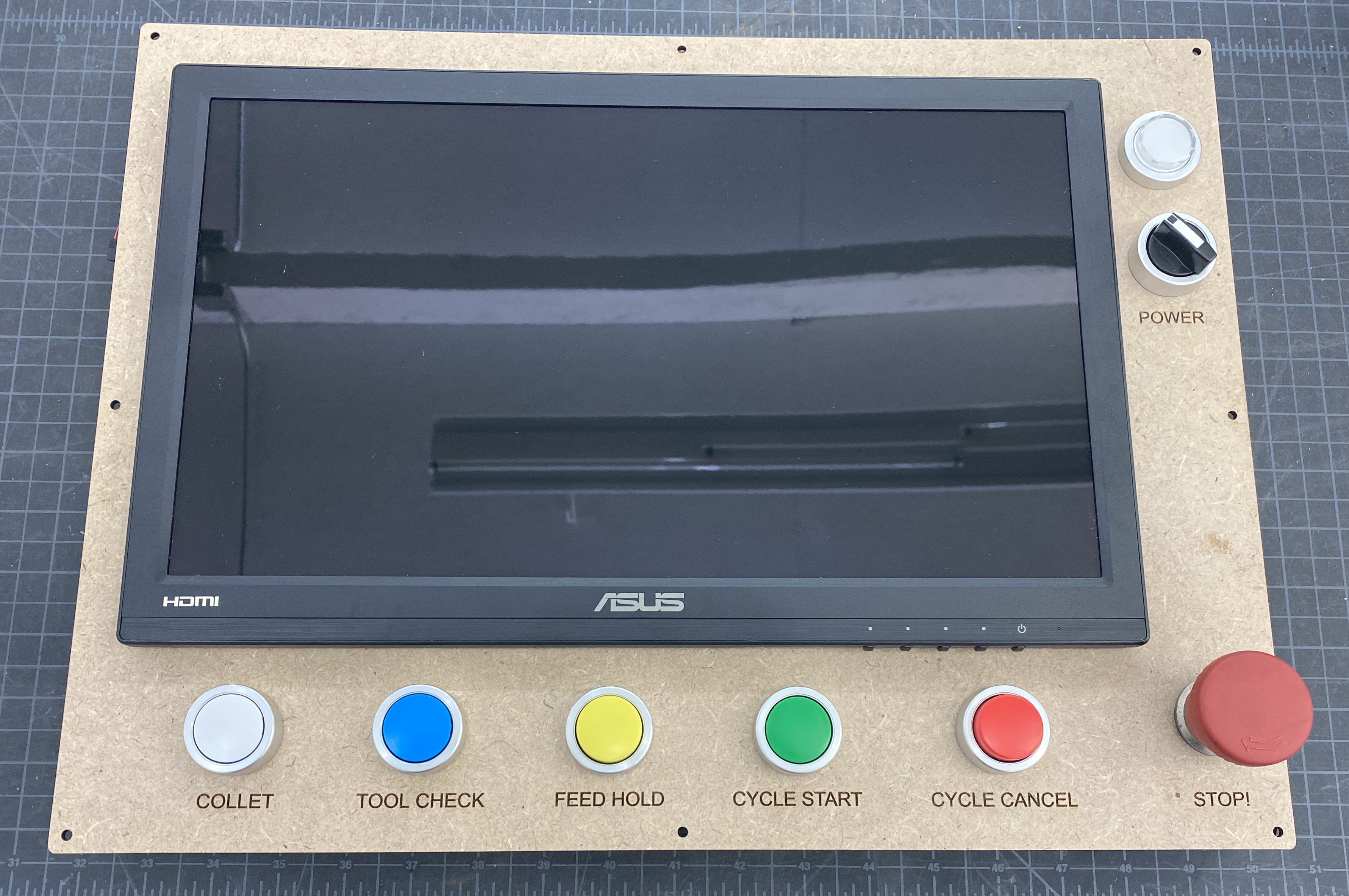
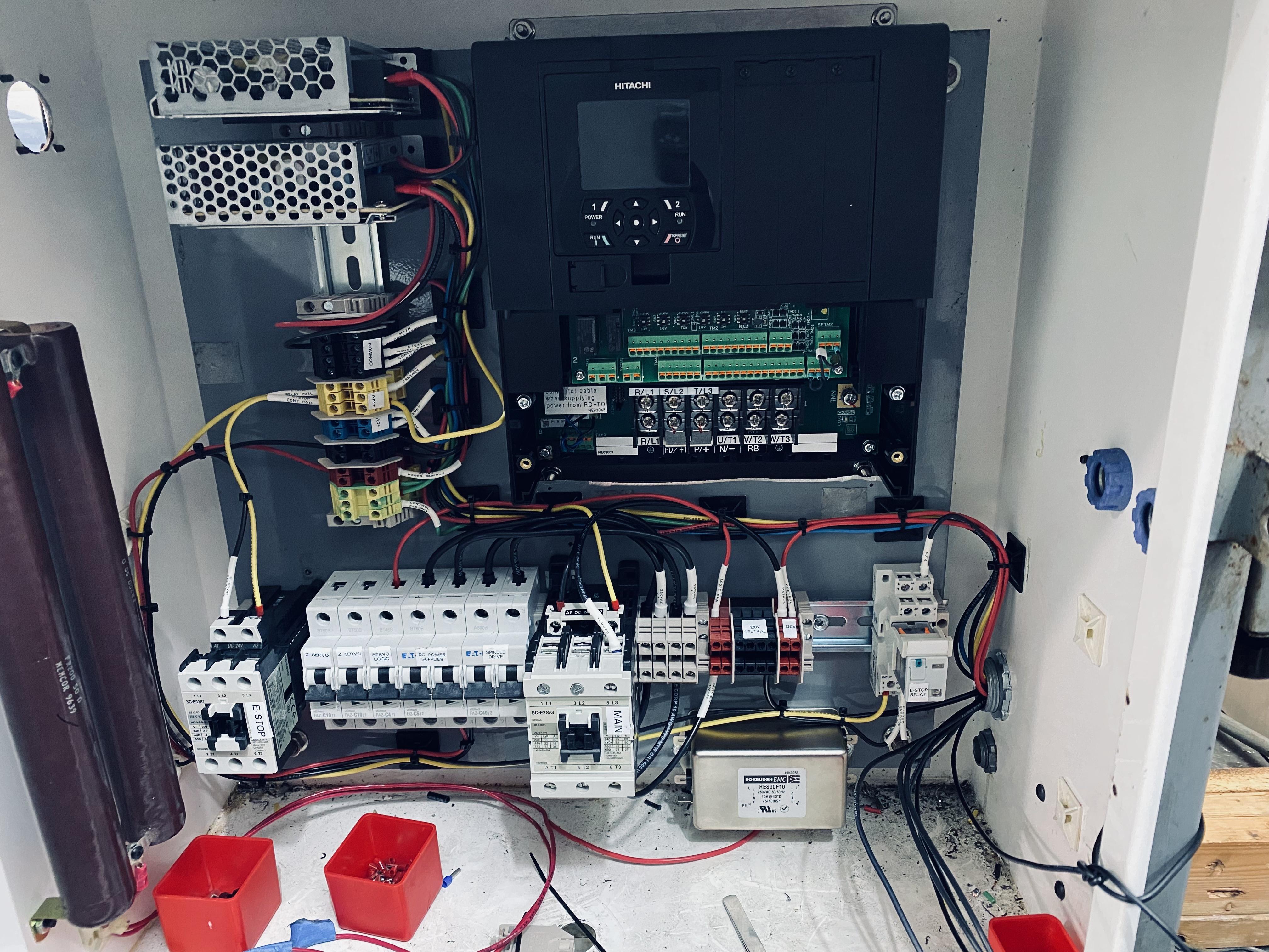
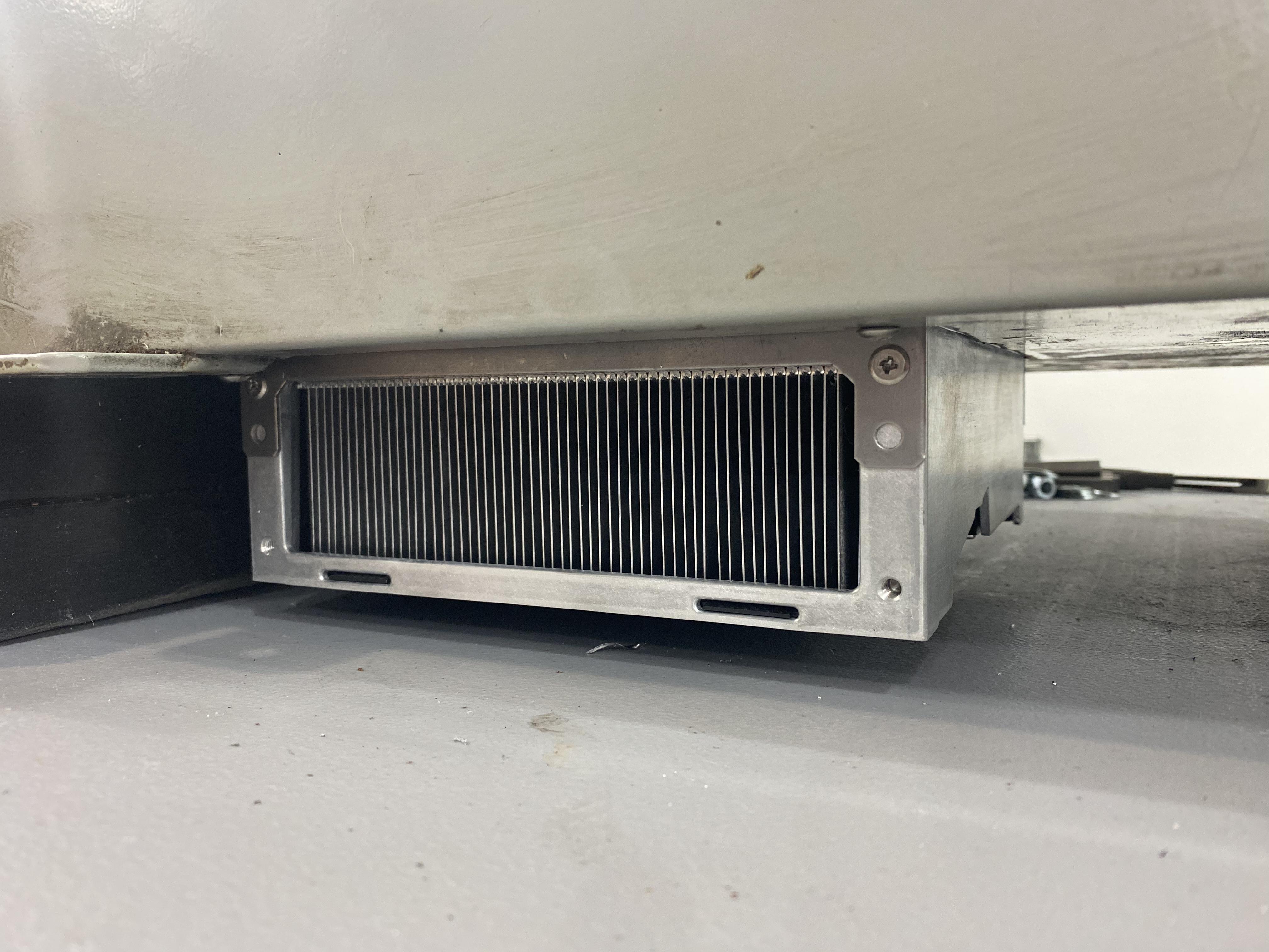
The Hitachi VFD is able to be mounted through the back of the cabinet, placing the cooling fans and heat sink outside. I’ll stand the cabinet off the side of the machine about 3”. Chips shouldn’t be a problem because it’s under the chip tray.
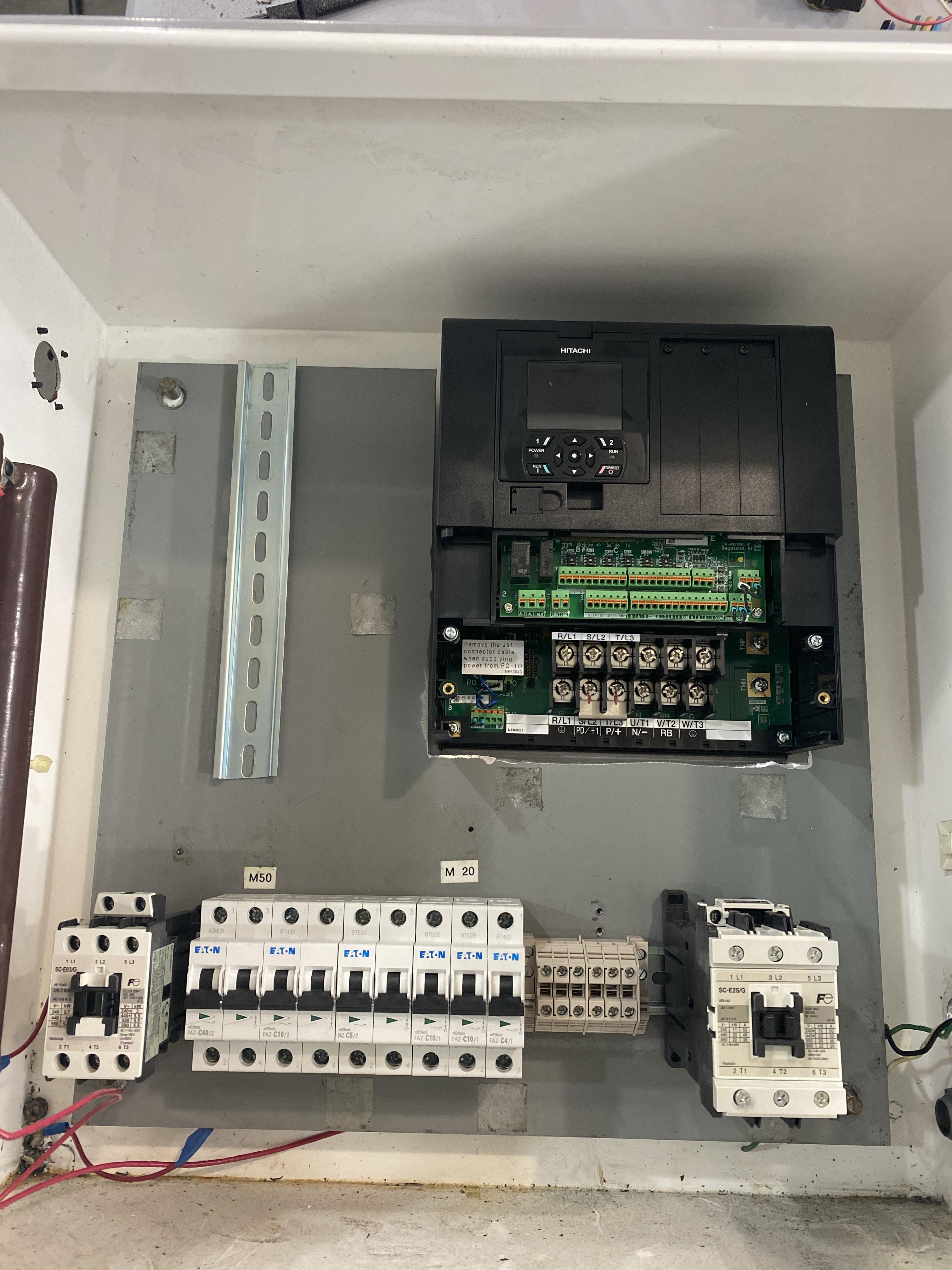
It has ball screws already. I’m replacing an existing Fagor CNC control. Tools mount on the gang block. I’m not sure about how that all works yet. I have some learning to do.
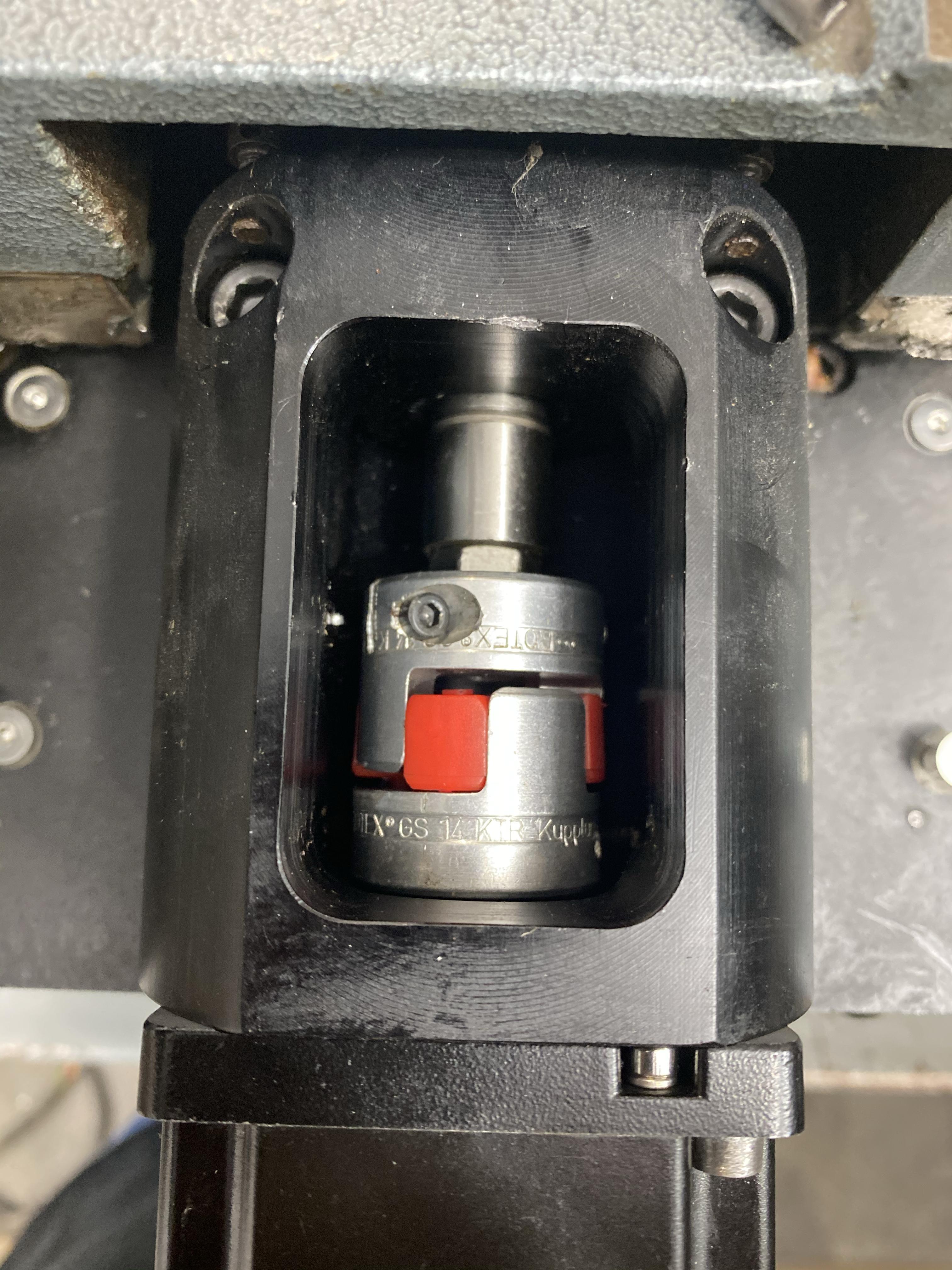
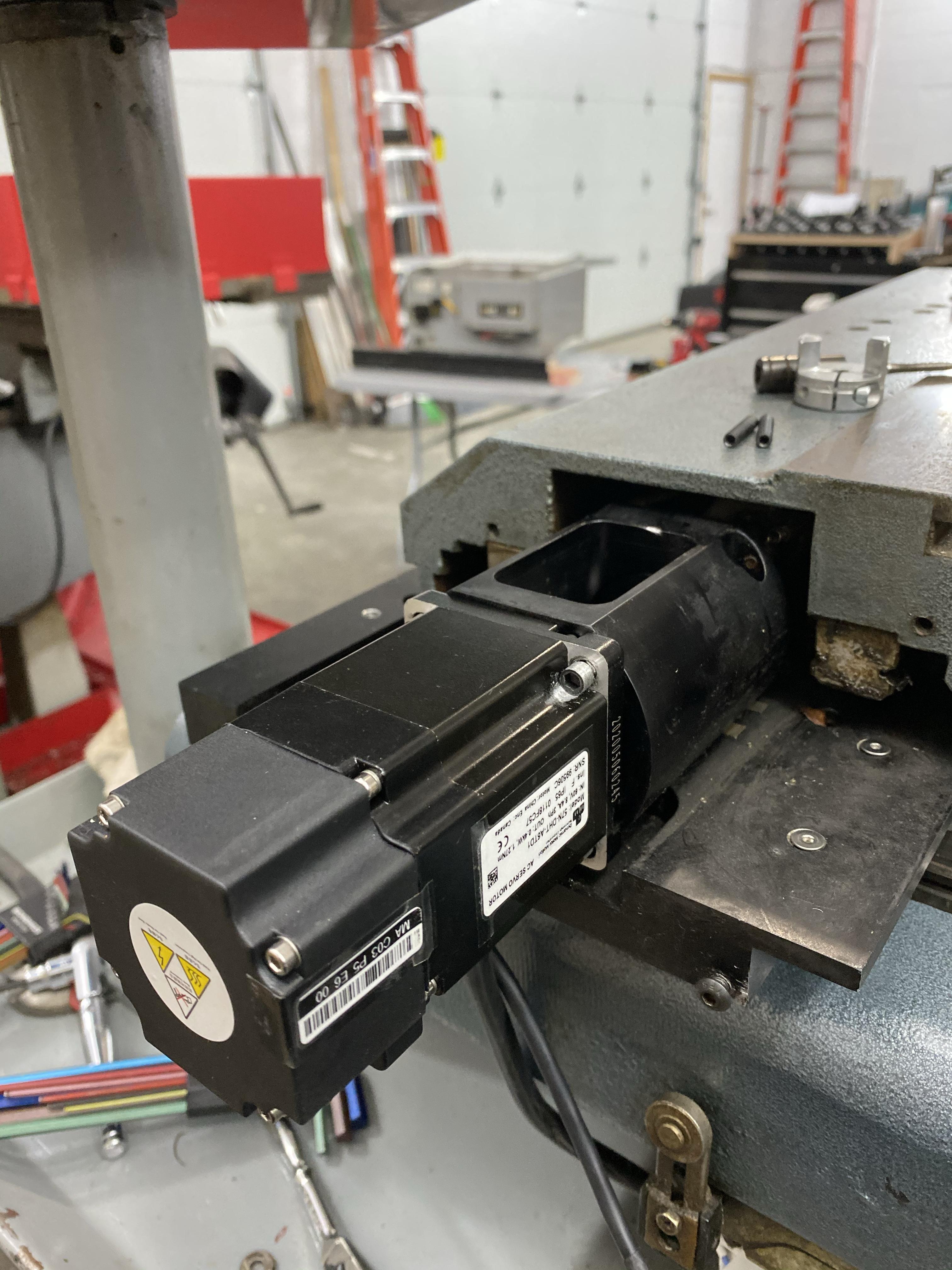
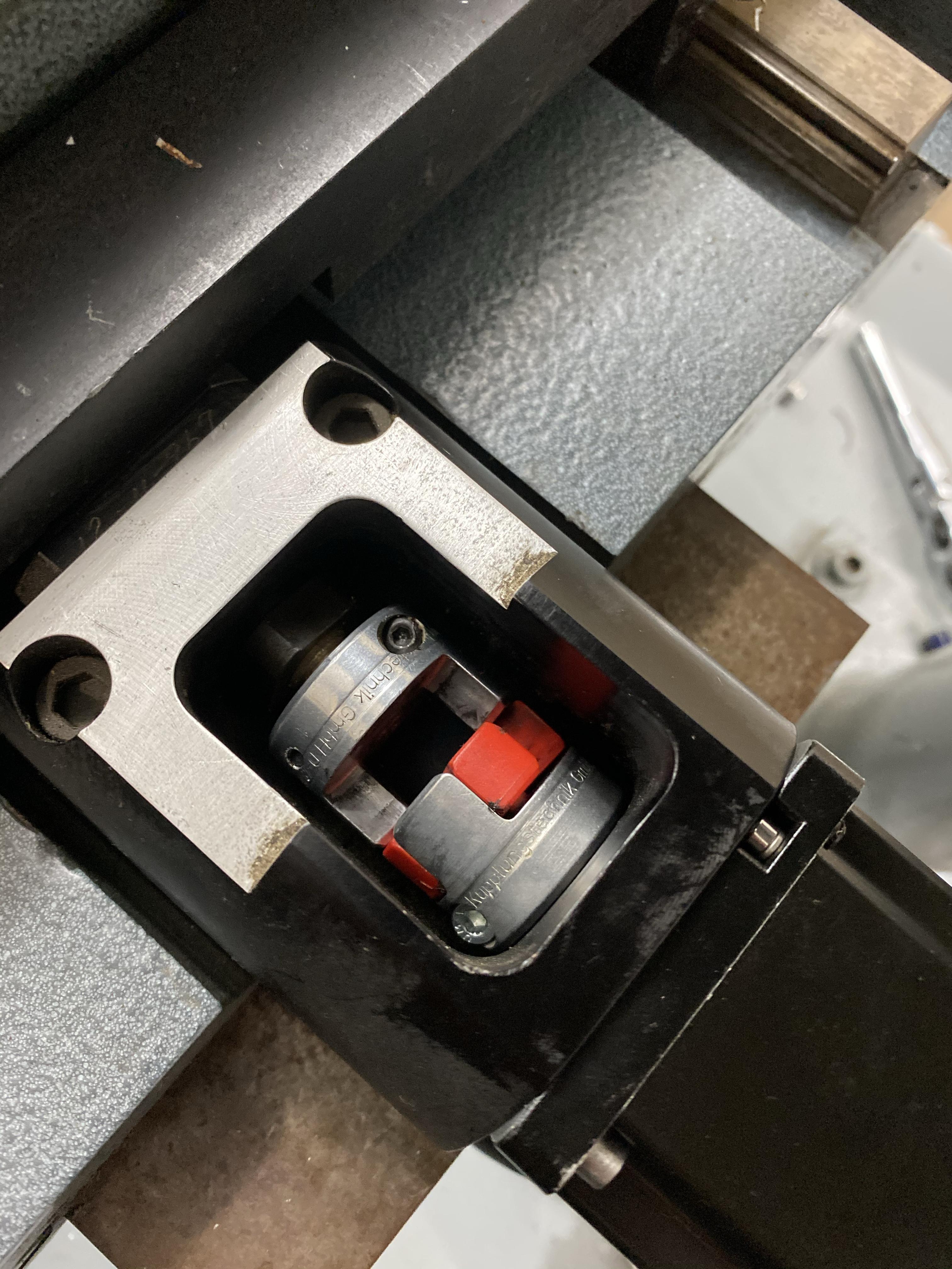
DMM AC servos arrived today. I did a lot of measuring prior to ordering. I knew they were close. They are! The original servos had 3/8” shafts. I found a 1/4 coupler of the same style. Worked great with the DMM’s 1/4” shaft. I had to turn down the heads of the socket head cap screws so they would go in to the bracket straight.
The X axis bracket is going to have to have about 0.4” milled off so the coupler will engage. I’m thinking I can modify the existing part. Not sure about extending the existing threaded mounting holes further in.. I may have to make a new bracket.
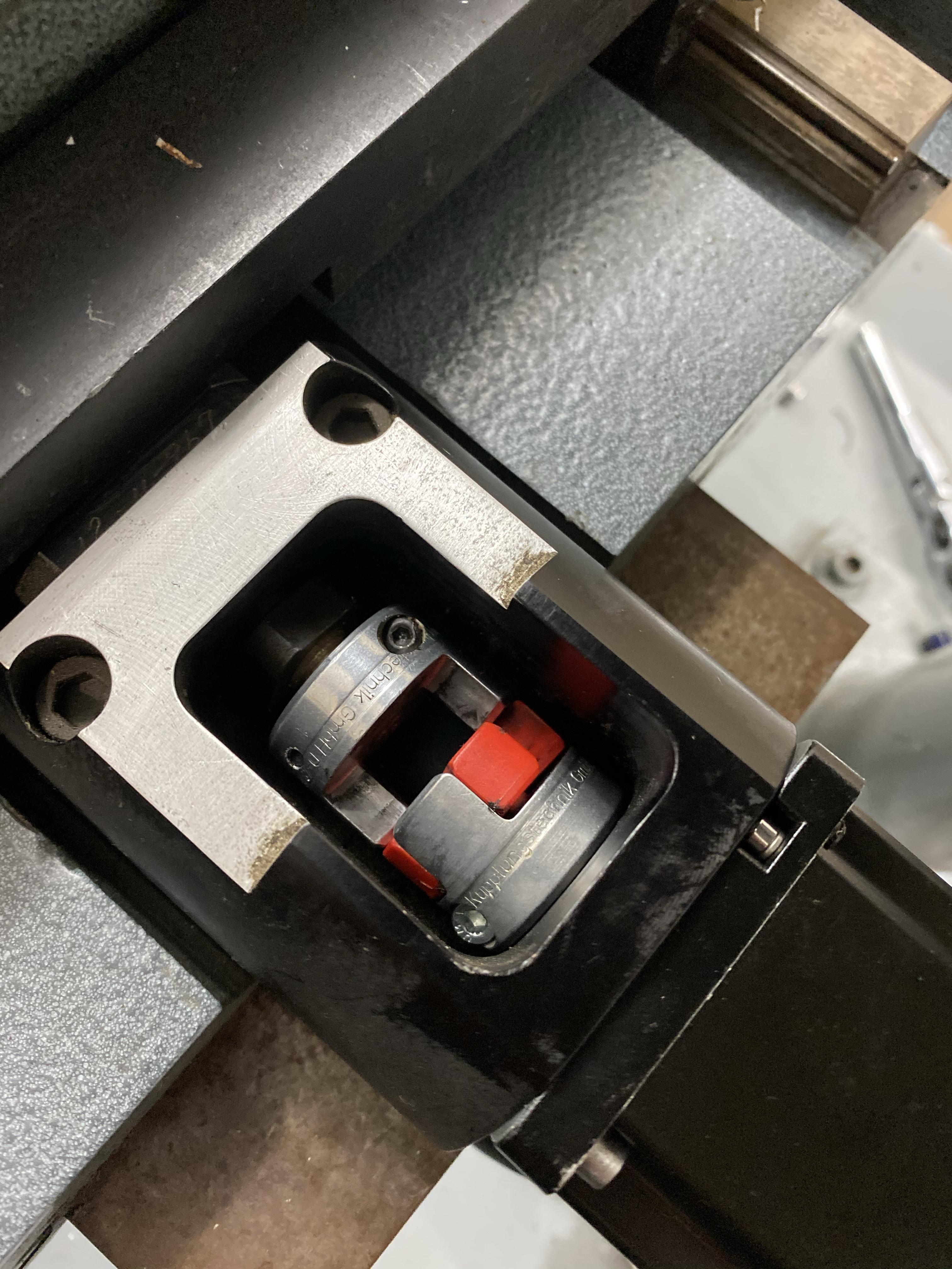
Line scratched showing where motor would mount up:
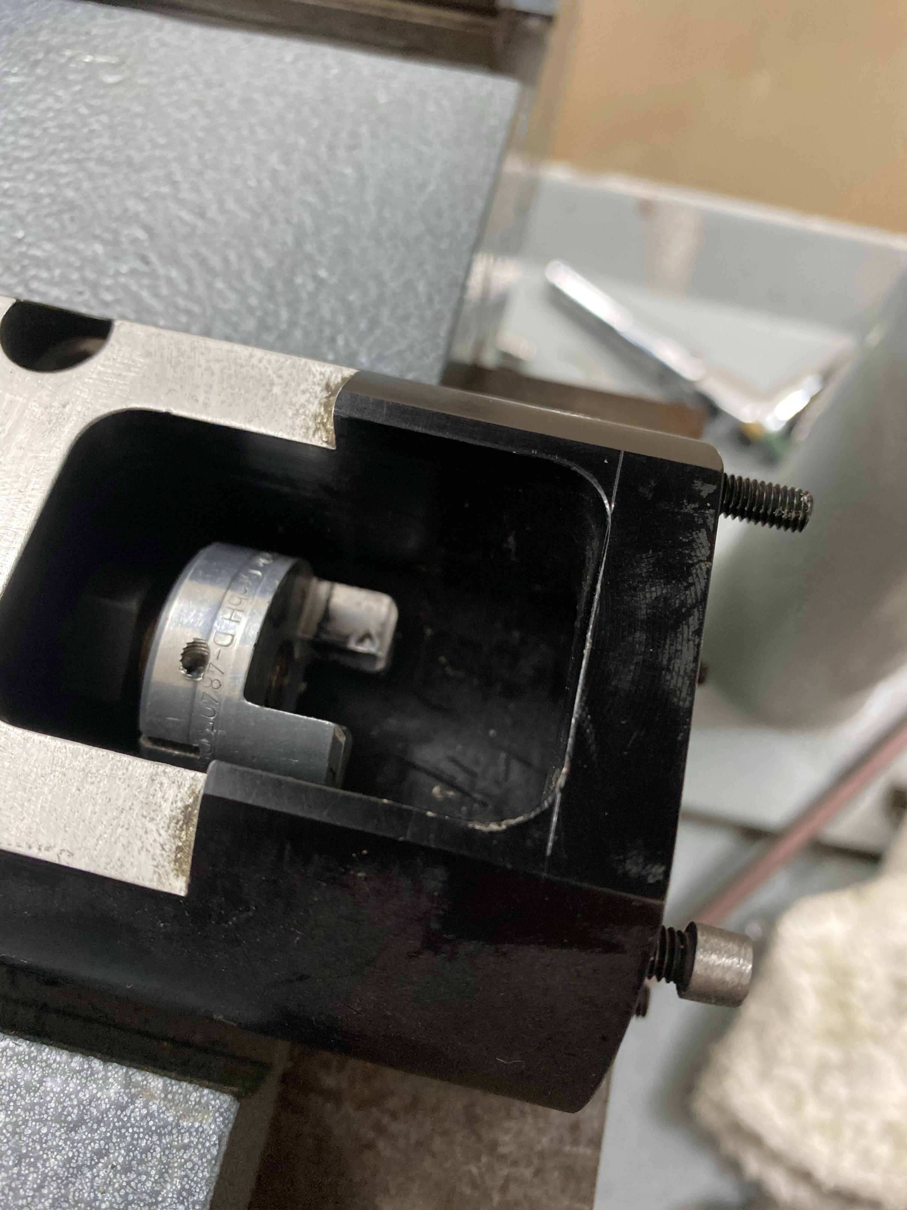
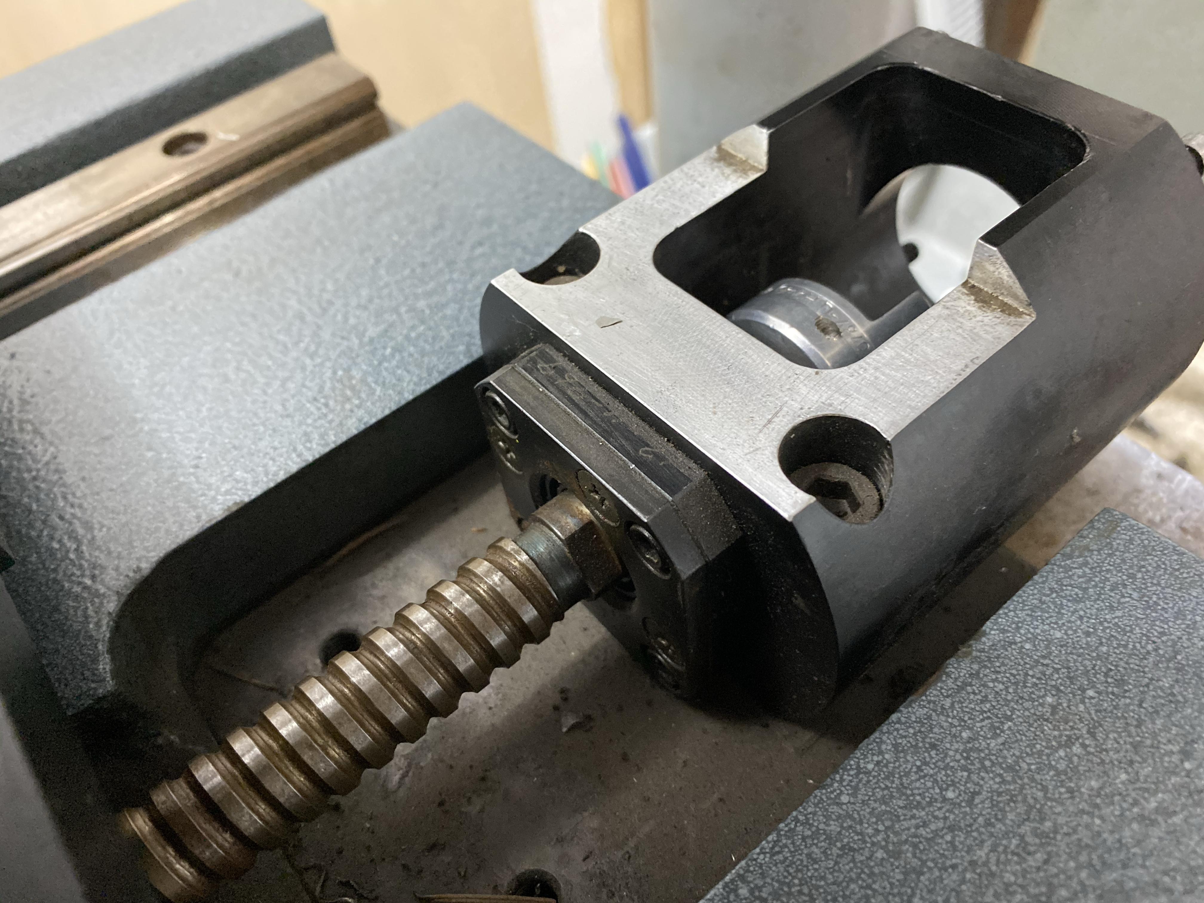
The Z axis coupler has a much smaller gap. I think it will need to be closed up, too.
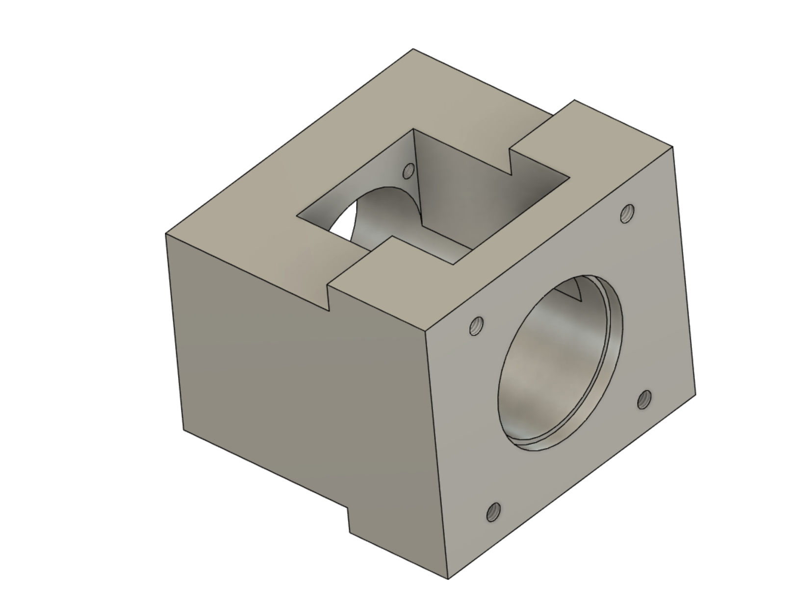
Got the part modeled.
Original motor mount:
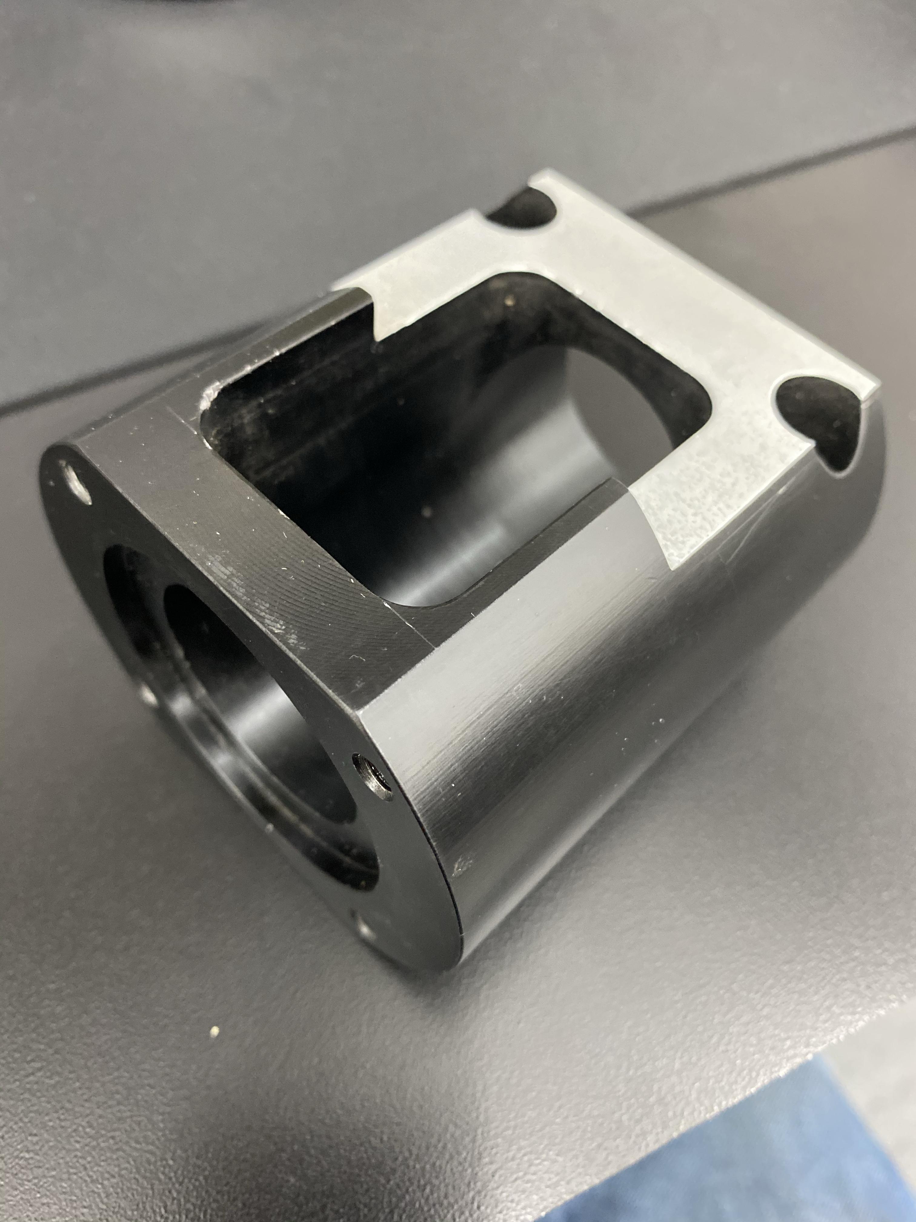
All I have on hand is some 3.5” round stock. This is definitely the most complicated (feature rich?) part I’ve made. I’m sure the first will be a test part.
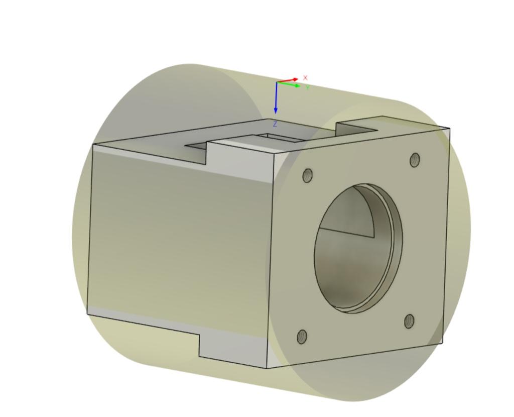
I ordered a 3 x 3.5” x 12” bar from Xometry. Hopefully I’ll only use a 3” chunk of it for the final part and have plenty left for the Z motor mount.
edit: forgot the mounting holes earlier.
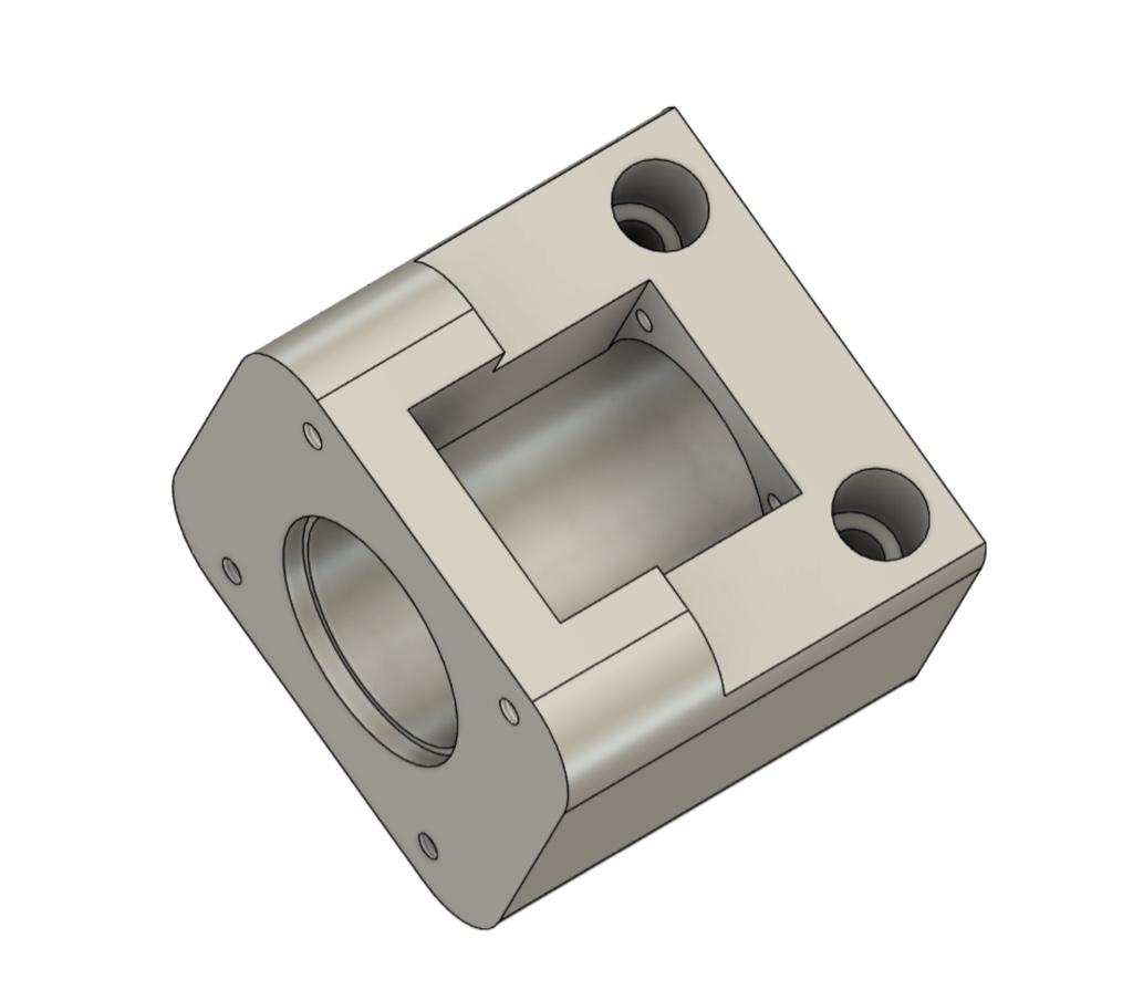
Starting to get the components laid out. I’d like to get everything in the existing two enclosures.
Spindle drive and AC components:
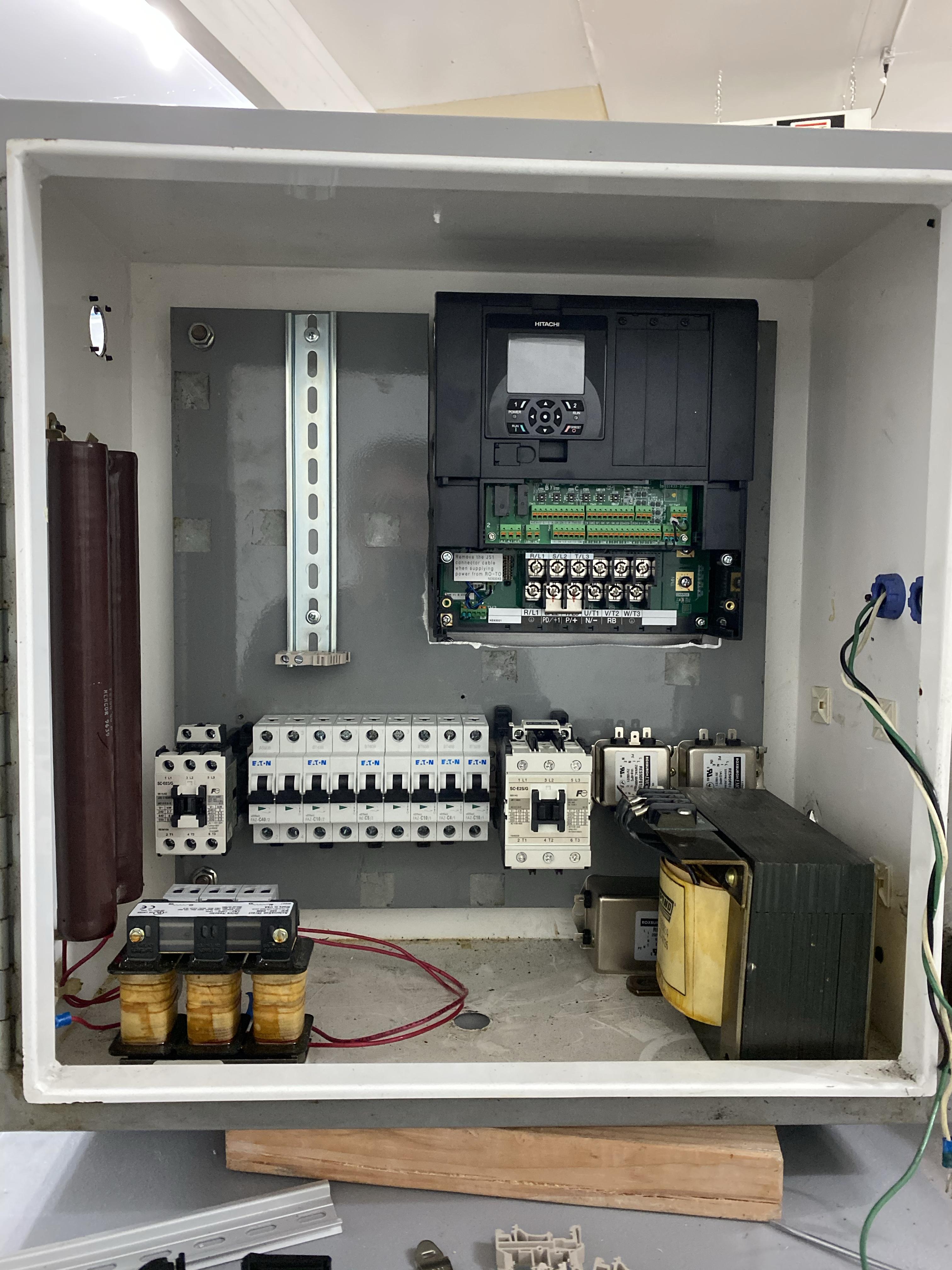
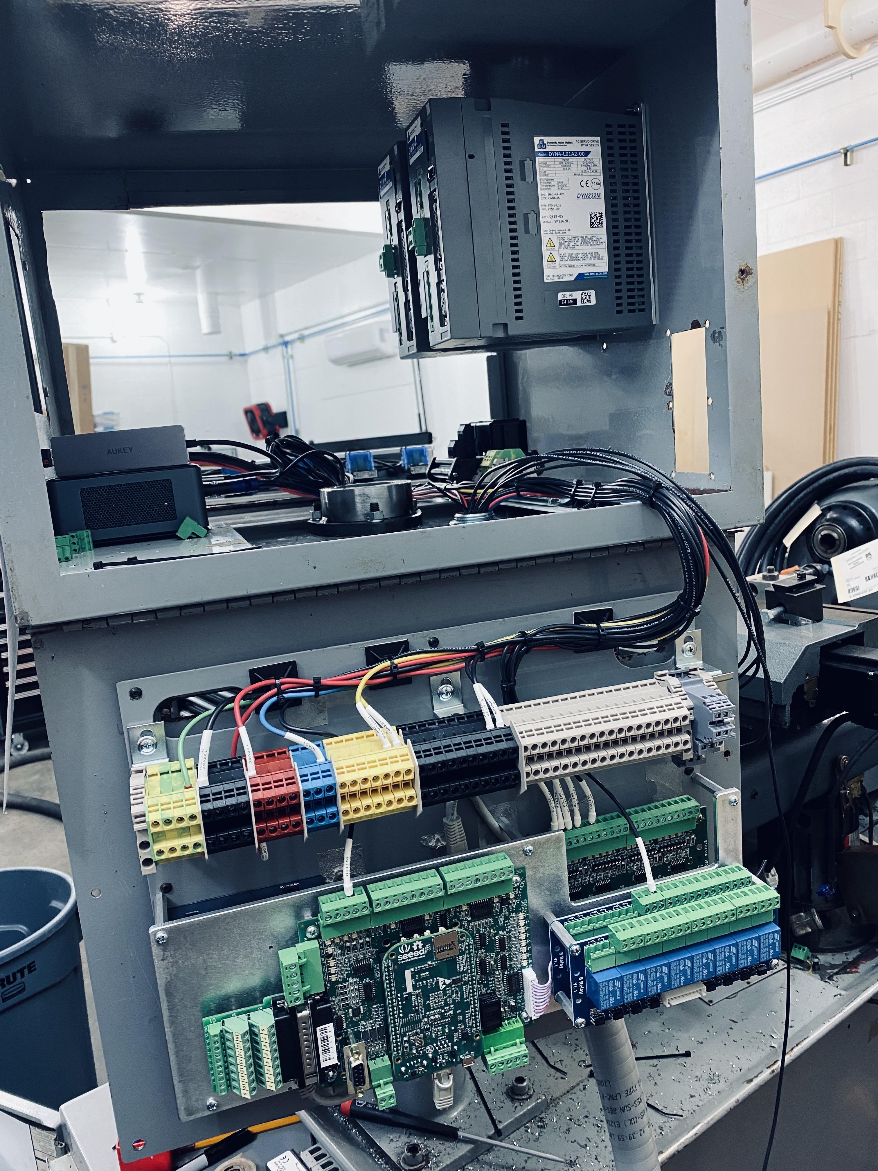
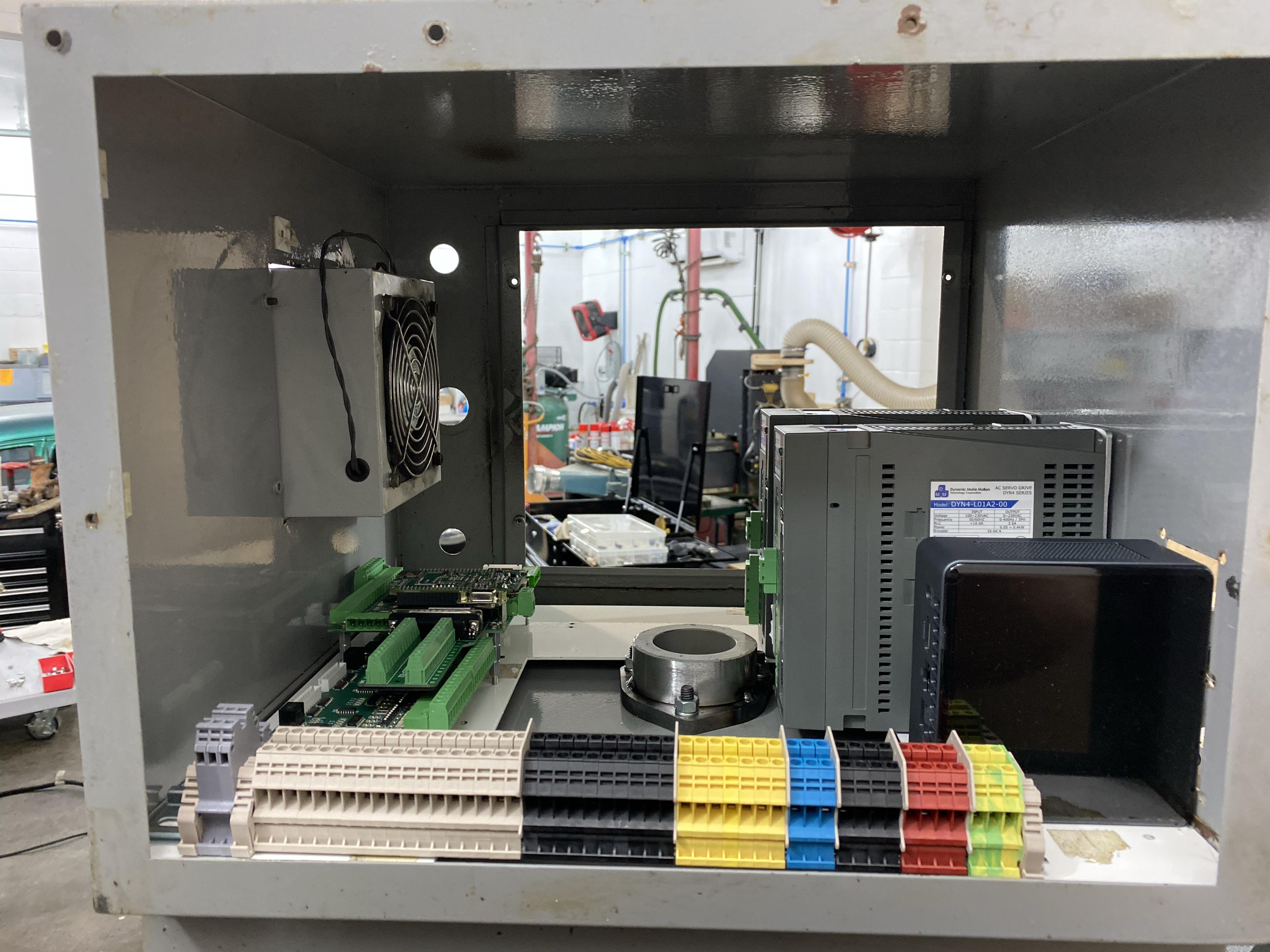
Control and servo drives in the control panel enclosure:
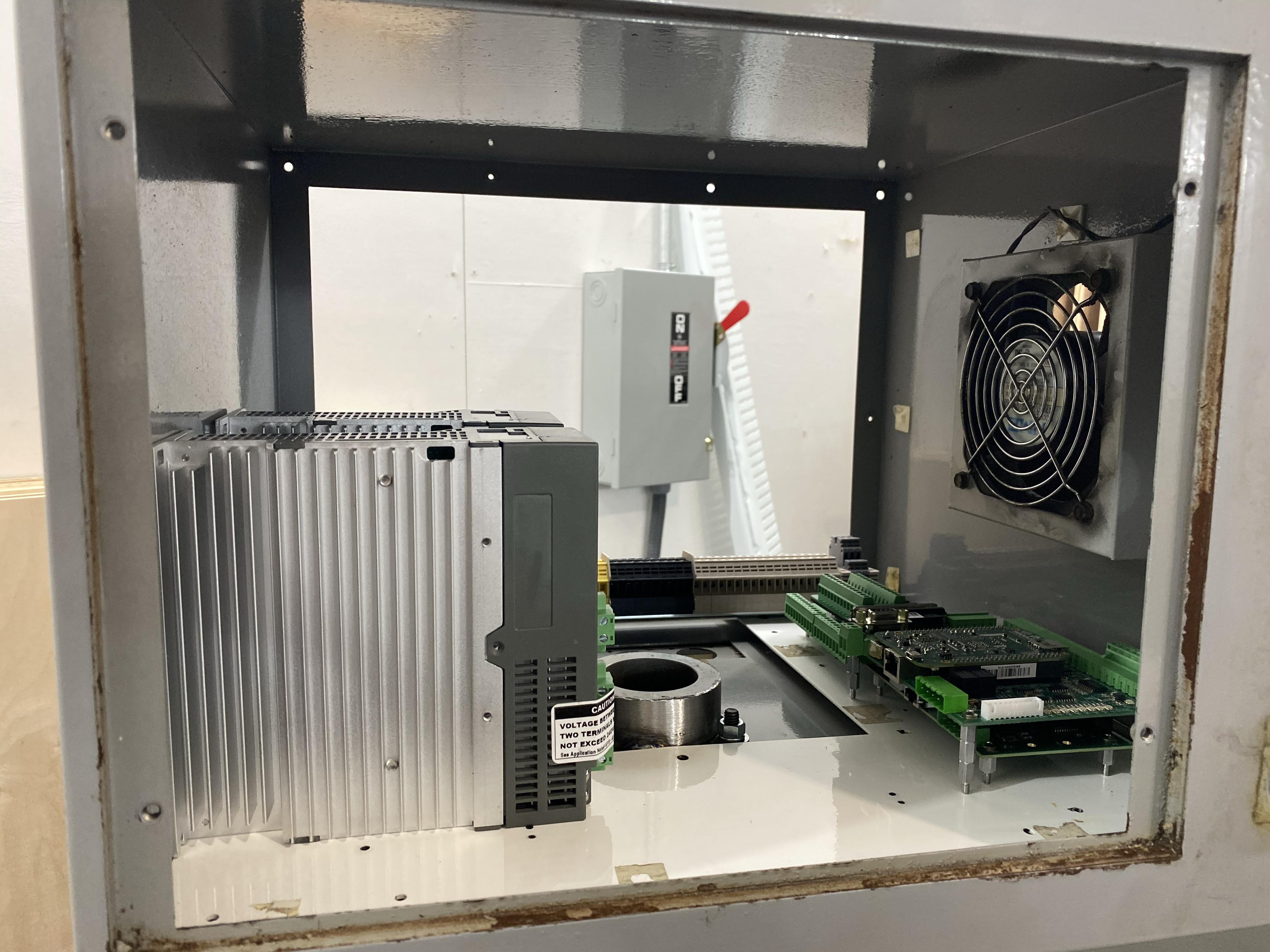
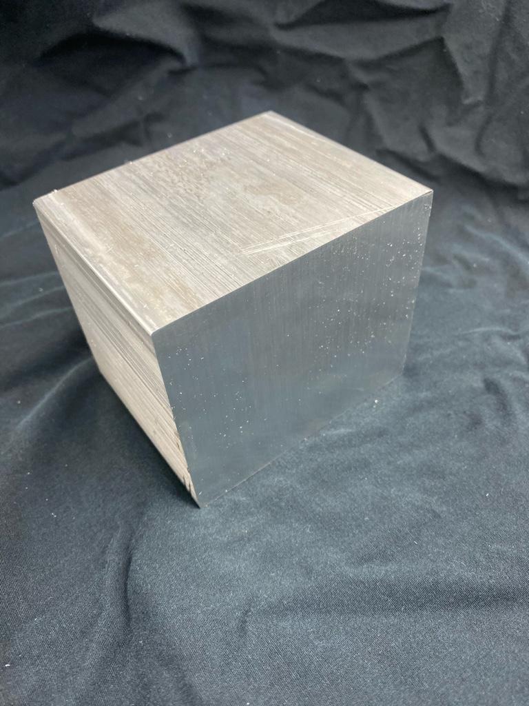
The first servo motor mount is coming along. What I started with 3x3x3.5:
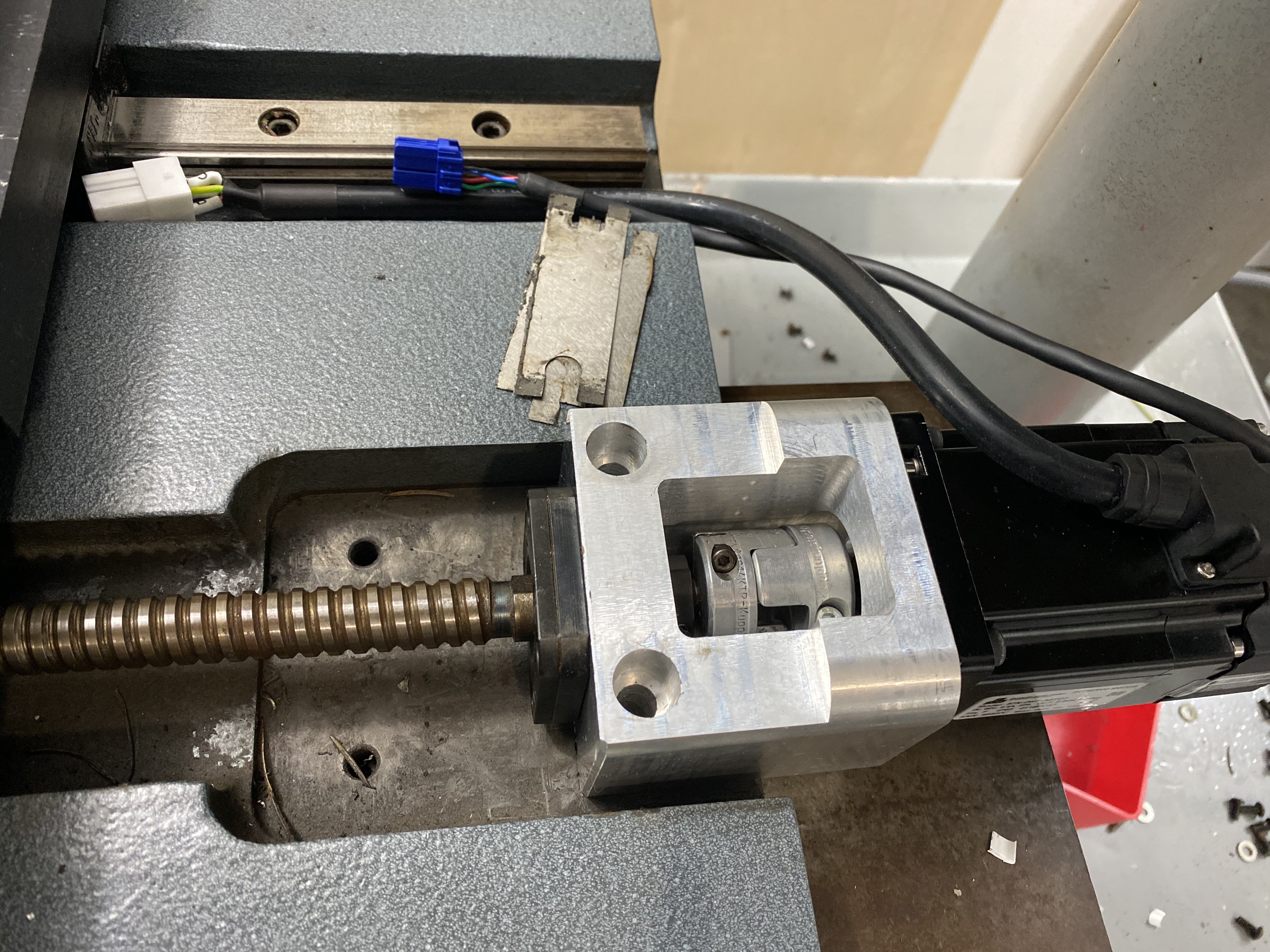
Close to fitting correctly. Need to shave a couple faces.
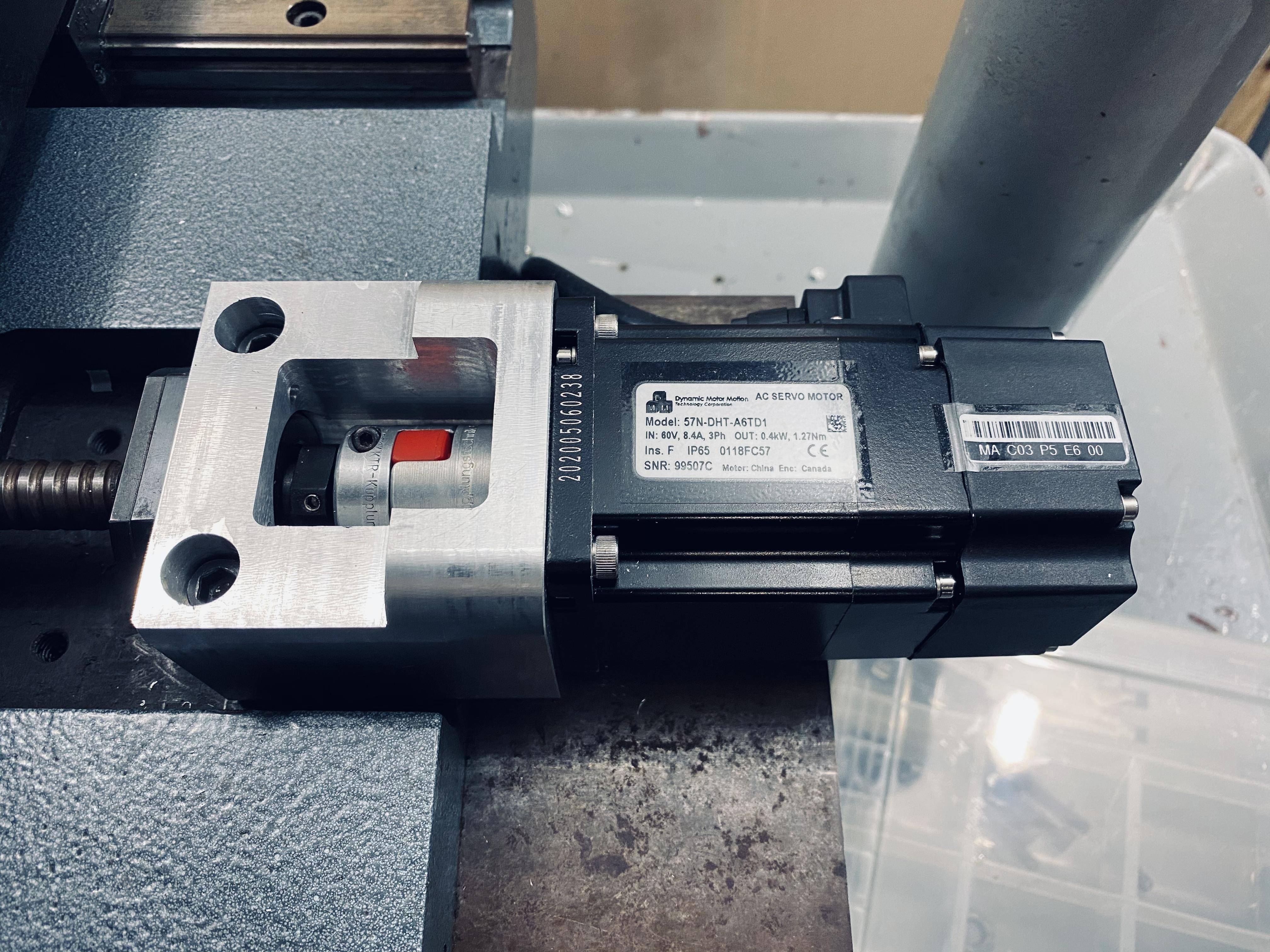
Finally finished a few adjustments on the servo mount. All went together nicely. I’m new to this cnc machining. Overall, quite happy with it. Bonus is, it will do the job! On to the next.
What I started with:
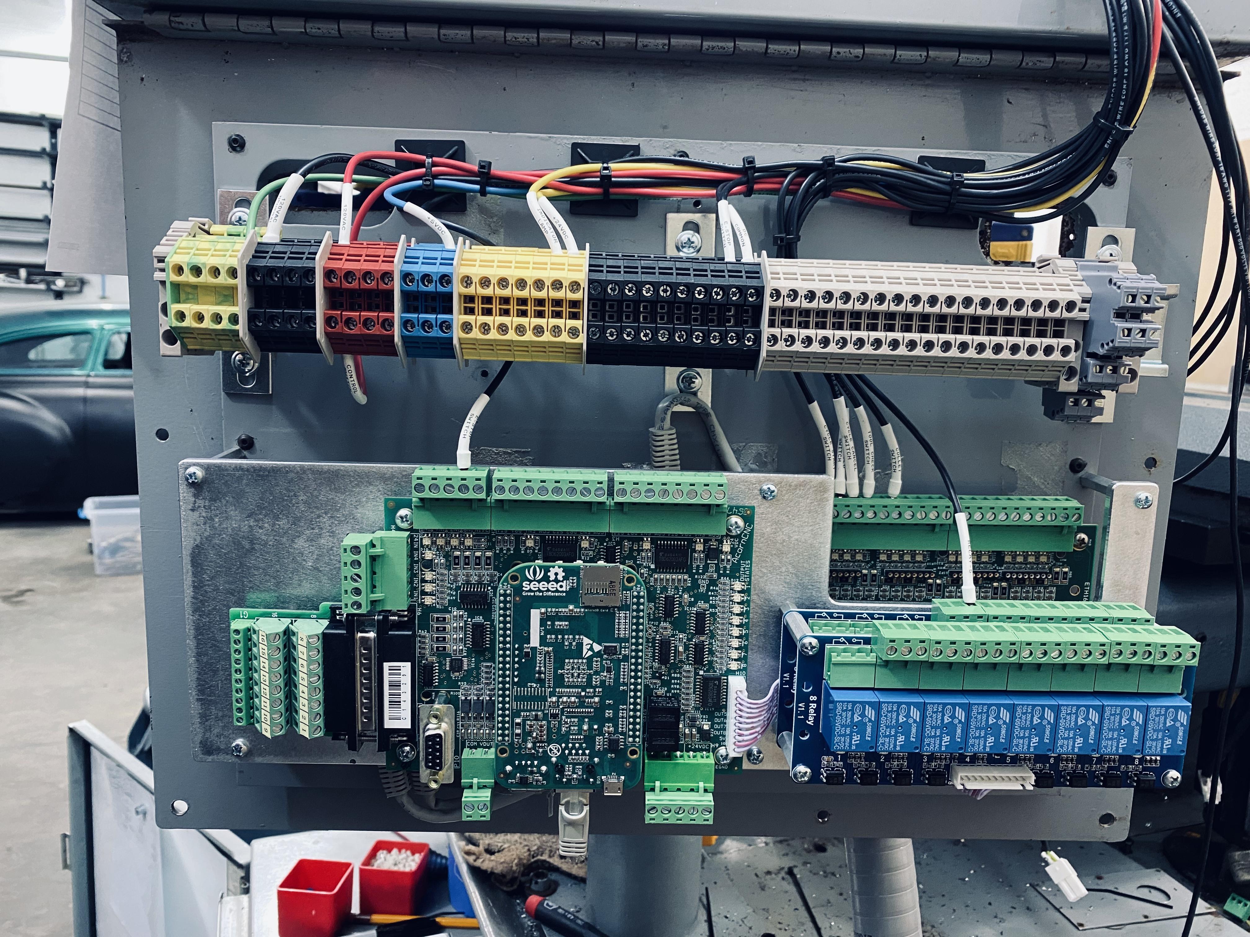
Control electronics starting to come together.
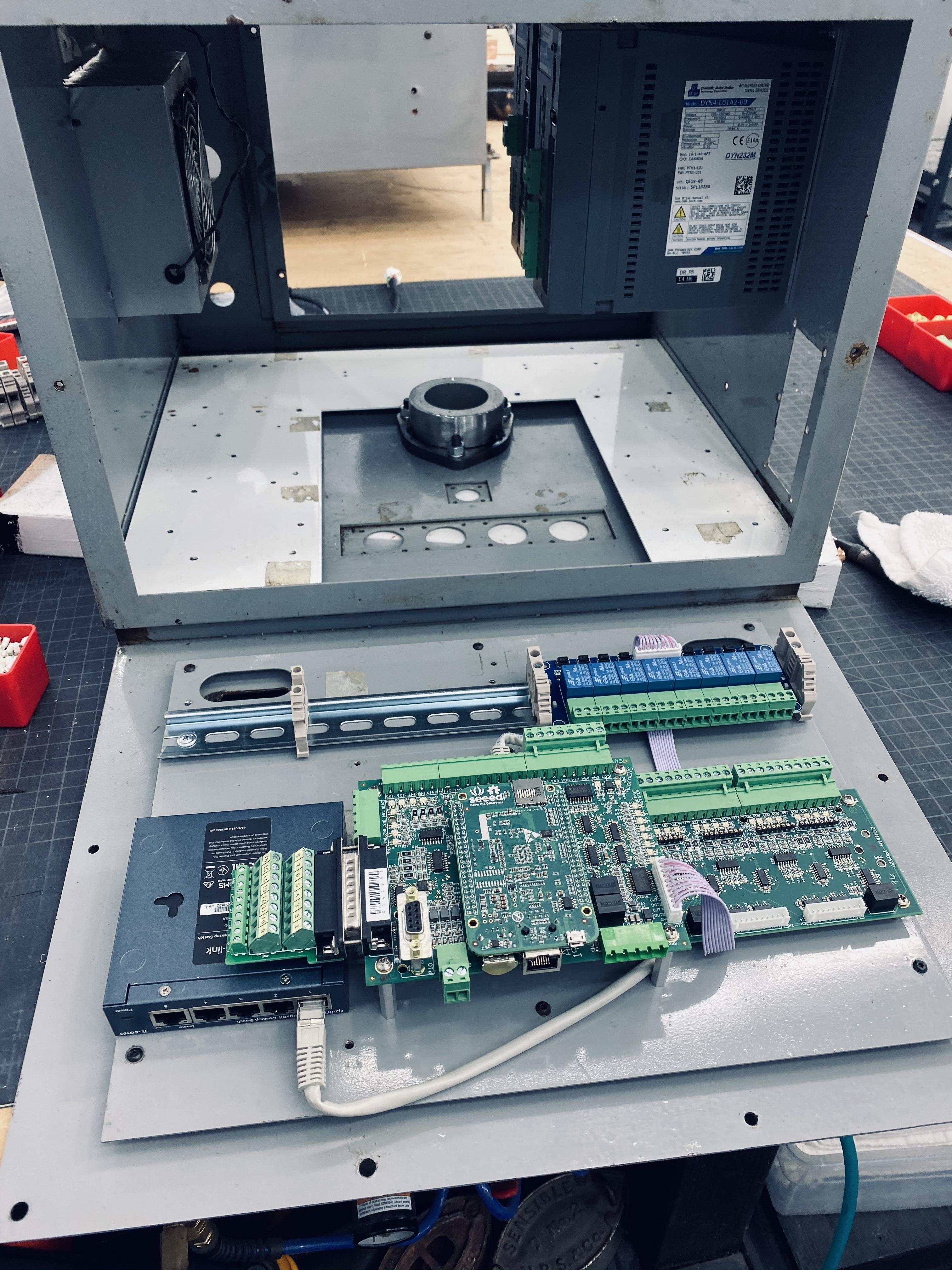
It’s always a challenge fitting and mounting all of the components, especially when using the existing enclosures. Came up with a second tier on the HMI rear door. This is where the original electronics were. Turned out well. Everything is secure and the terminals and I/O status LED’s on the lower board are still accessible and visible. Lower layer is gigabit Ethernet switch and 1616 Ethernet I/O expansion. Upper layer is Acorn control board and 8 output interposing relay board.
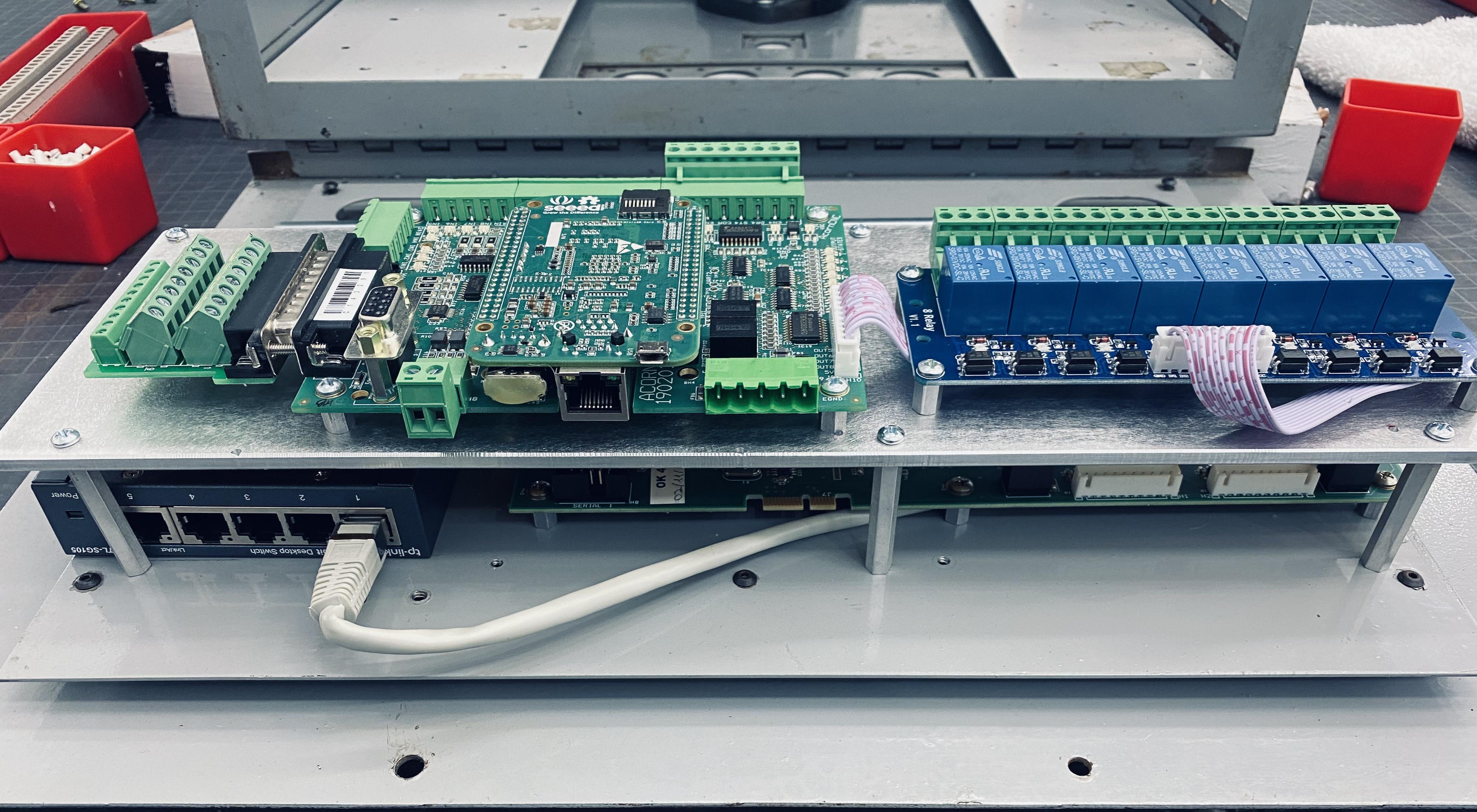
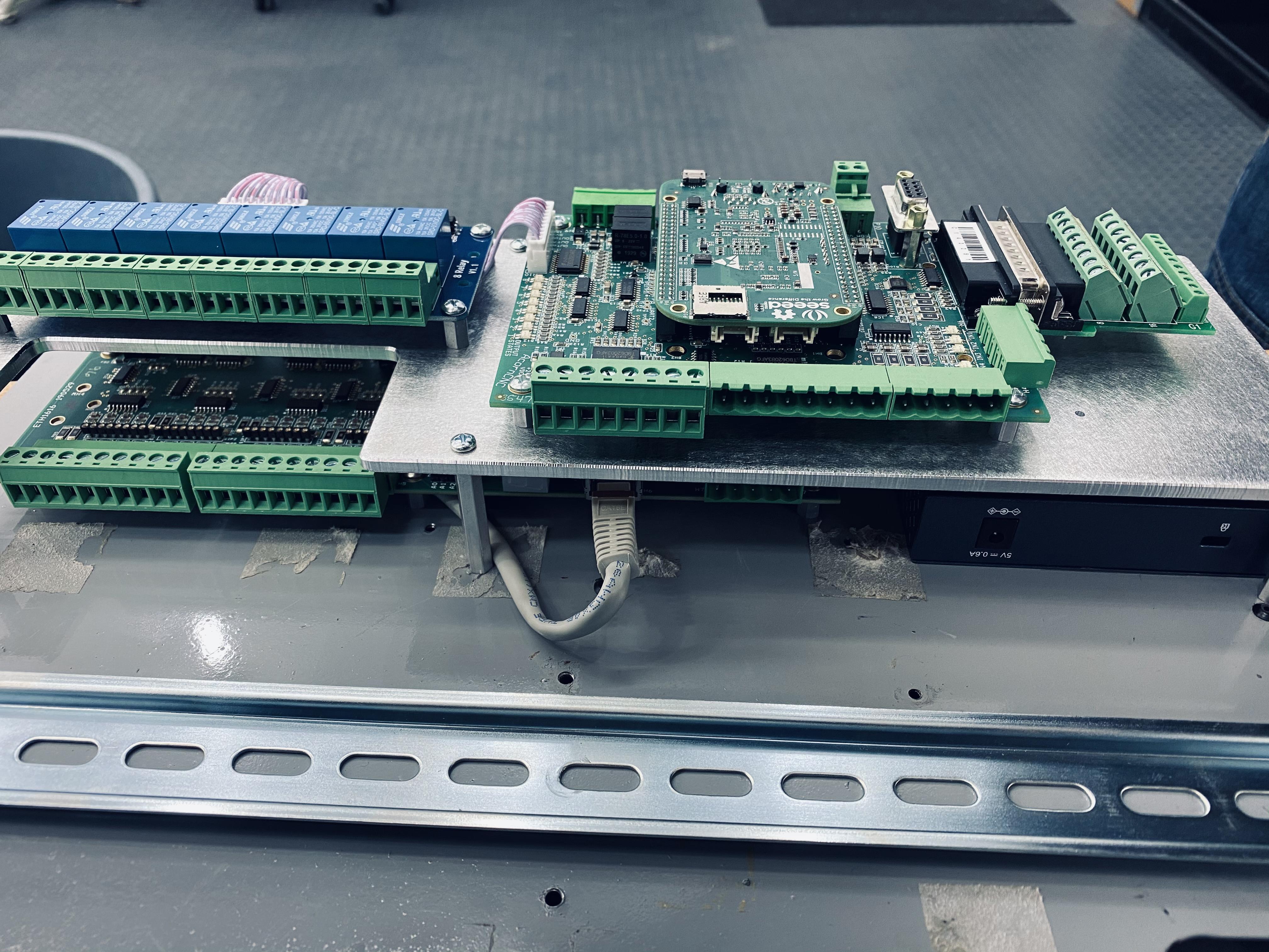
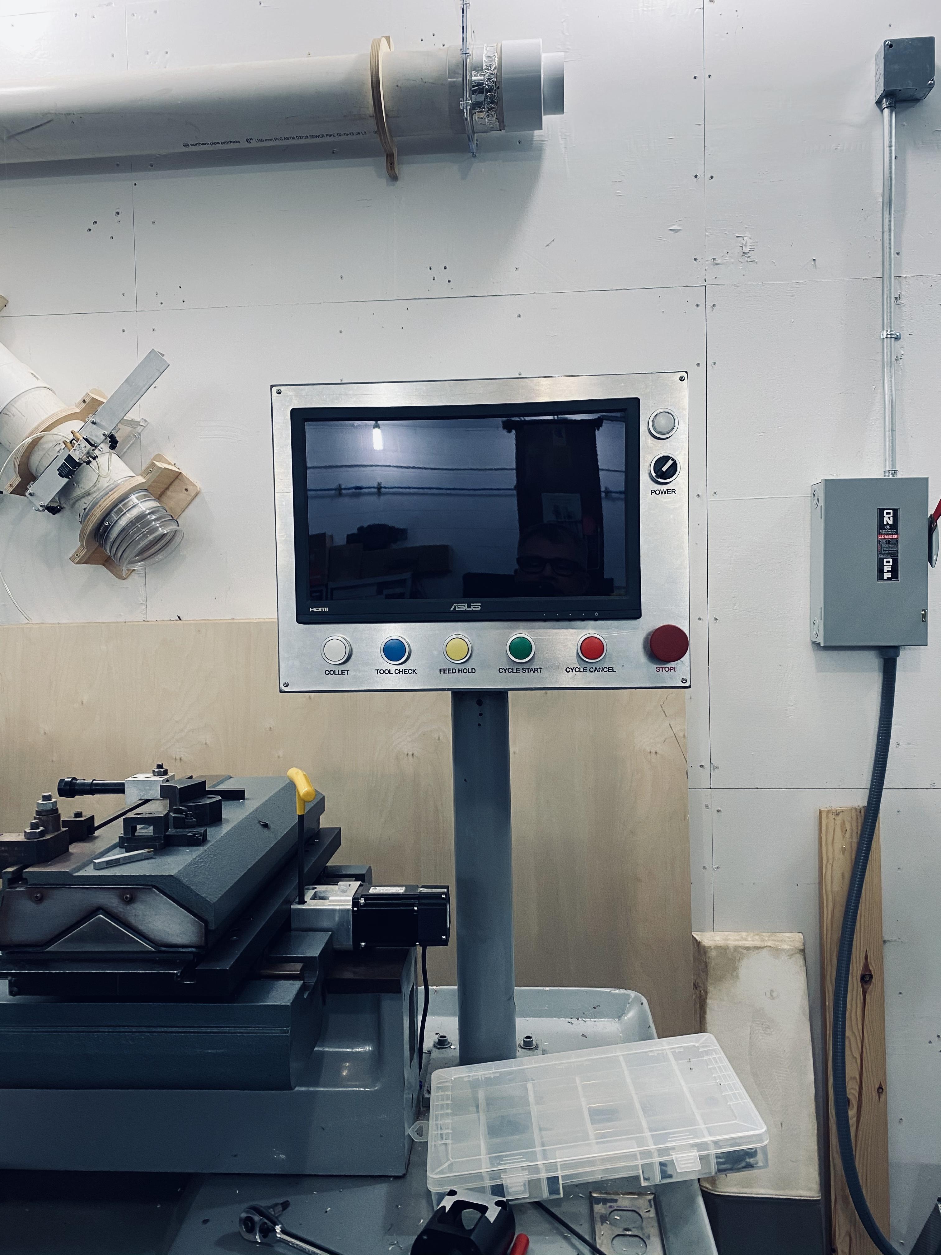
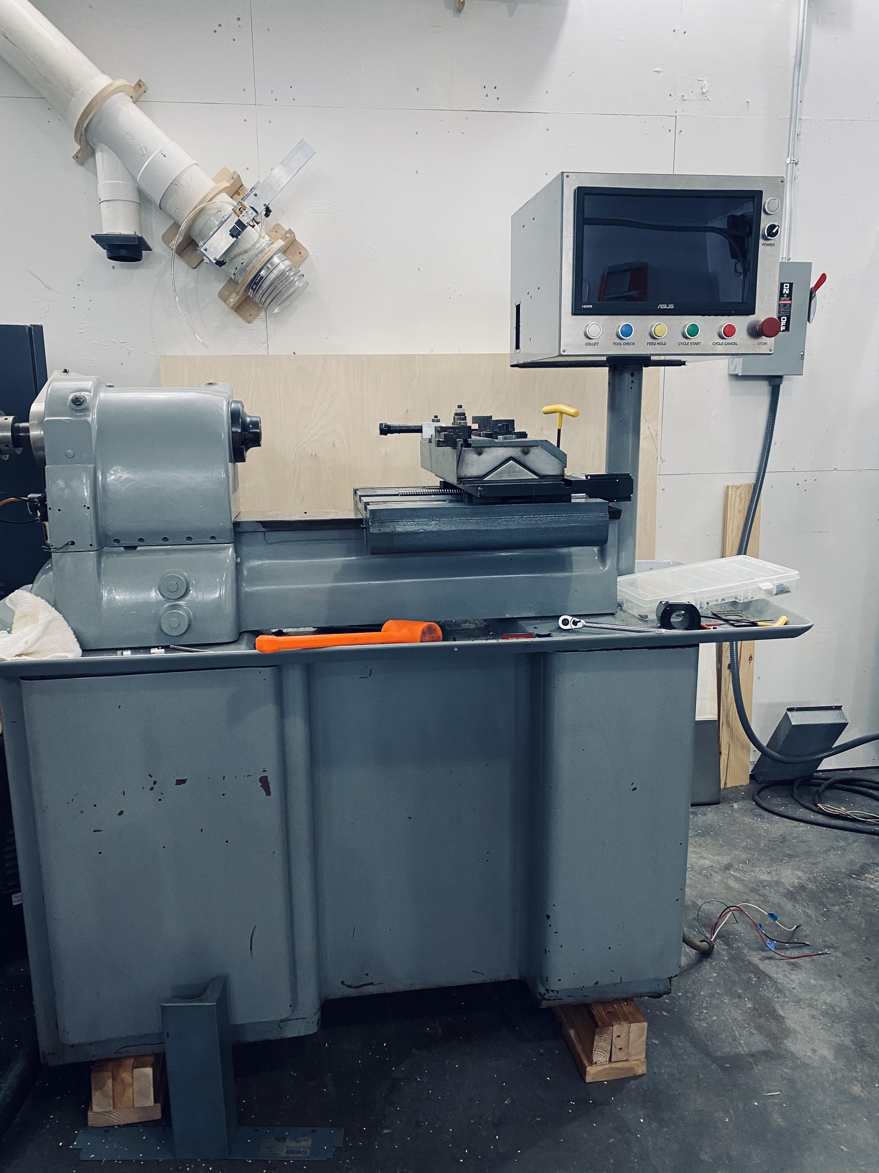
Control panel sitting on the lathe.

Before we loaded it on the trailer:

Hardinge lathe with Upgrade Technologies Accuslide CNC conversion with Fagor control. I will be installing new servos and Centroid control. Very similar to my mill conversion. Should make a really nice CNC lathe for my shop.
Got the lathe unloaded off the trailer and roughly in its resting place. It will stay on the cribbing until the controls are installed. Overall it’s in excellent condition. Was quite dirty. Still some cleaning left. Starting to sort out the existing control circuits. Most of the new control components are ordered. The existing Accuslide CNC conversion mechanical components look to be in great condition. I’ll have to source or make a few way cover parts that are missing. I have a 3 jaw chuck on the way.

I sorted out how to move the Accuslide away from the spindle. This will allow me full use of the X axis travel.

While waiting for parts to arrive, I made a mdf sample of the control panel layout. Test piece is made out of 1/8 mdf on the laser to check dimensions, layout, etc. I think this is what I’ll be going with.

Touchscreen arrived. Got a great deal on Amazon Warehouse deals. Almost half price.
MDF mockup looks good.
The Hitachi VFD is able to be mounted through the back of the cabinet, placing the cooling fans and heat sink outside. I’ll stand the cabinet off the side of the machine about 3”. Chips shouldn’t be a problem because it’s under the chip tray.


It has ball screws already. I’m replacing an existing Fagor CNC control. Tools mount on the gang block. I’m not sure about how that all works yet. I have some learning to do.
DMM AC servos arrived today. I did a lot of measuring prior to ordering. I knew they were close. They are! The original servos had 3/8” shafts. I found a 1/4 coupler of the same style. Worked great with the DMM’s 1/4” shaft. I had to turn down the heads of the socket head cap screws so they would go in to the bracket straight.
The X axis bracket is going to have to have about 0.4” milled off so the coupler will engage. I’m thinking I can modify the existing part. Not sure about extending the existing threaded mounting holes further in.. I may have to make a new bracket.

Line scratched showing where motor would mount up:


The Z axis coupler has a much smaller gap. I think it will need to be closed up, too.


Got the part modeled.
Original motor mount:


All I have on hand is some 3.5” round stock. This is definitely the most complicated (feature rich?) part I’ve made. I’m sure the first will be a test part.

I ordered a 3 x 3.5” x 12” bar from Xometry. Hopefully I’ll only use a 3” chunk of it for the final part and have plenty left for the Z motor mount.
edit: forgot the mounting holes earlier.

Starting to get the components laid out. I’d like to get everything in the existing two enclosures.
Spindle drive and AC components:

Control and servo drives in the control panel enclosure:


The first servo motor mount is coming along. What I started with 3x3x3.5:

Close to fitting correctly. Need to shave a couple faces.
Finally finished a few adjustments on the servo mount. All went together nicely. I’m new to this cnc machining. Overall, quite happy with it. Bonus is, it will do the job! On to the next.

What I started with:

Control electronics starting to come together.

It’s always a challenge fitting and mounting all of the components, especially when using the existing enclosures. Came up with a second tier on the HMI rear door. This is where the original electronics were. Turned out well. Everything is secure and the terminals and I/O status LED’s on the lower board are still accessible and visible. Lower layer is gigabit Ethernet switch and 1616 Ethernet I/O expansion. Upper layer is Acorn control board and 8 output interposing relay board.


Control panel sitting on the lathe.


