- Joined
- Dec 28, 2023
- Messages
- 6
Hi,
I am setting up a mill to cut spiral fluting on a 24" rifle barrel.
I have a PM949 mill and a BS2 dividing head from Precision Matthews.
The BS2 came with 12 gears with the following tooth count.
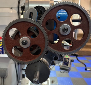
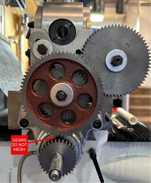
If I use those gears A (64 tooth) / D (32 tooth) and B (72 tooth) / C (48 tooth) as shown below do not mesh regardless of configuration.

To my knowledge, there is no option that will get me an exact match based on the gears provided with the dividing head. I have tried going up and down in teeth for different gears and came up with one combination that meshed and created a 24.5" spiral which was very close to the 24" goal. The math did not work out for me when trying to reverse engineer.

As far as I can tell, none of the gear combinations that were an exact match are physically possible and are limited to those in green.

Am I going about determining which gears should be used correctly, and am I making any incorrect assumptions?
What adjustments should I make to create a 24" spiral in this instance?
Recommendations for how to approach this best in the future.
Thanks
I am setting up a mill to cut spiral fluting on a 24" rifle barrel.
I have a PM949 mill and a BS2 dividing head from Precision Matthews.
The BS2 came with 12 gears with the following tooth count.
- 100, 86, 72, 64, 56, 48
- 44, 40, 32, 28, 24, 24
| Determine the pitch of the helix (S), which is the length of one full spiral = length of the barrel | S=24" |
| Determine the value for use as (Ls), which is the TPI of the table lead screw (1:5) multiplied by the gear ratio of the dividing head (40) | Ls = 8
|
| Resolve fraction to two factors | |
| Raise each factor to higher terms that match available gears |
If I use those gears A (64 tooth) / D (32 tooth) and B (72 tooth) / C (48 tooth) as shown below do not mesh regardless of configuration.
To my knowledge, there is no option that will get me an exact match based on the gears provided with the dividing head. I have tried going up and down in teeth for different gears and came up with one combination that meshed and created a 24.5" spiral which was very close to the 24" goal. The math did not work out for me when trying to reverse engineer.
As far as I can tell, none of the gear combinations that were an exact match are physically possible and are limited to those in green.
Am I going about determining which gears should be used correctly, and am I making any incorrect assumptions?
What adjustments should I make to create a 24" spiral in this instance?
Recommendations for how to approach this best in the future.
Thanks