

-
Welcome back Guest! Did you know you can mentor other members here at H-M? If not, please check out our Relaunch of Hobby Machinist Mentoring Program!
You are using an out of date browser. It may not display this or other websites correctly.
You should upgrade or use an alternative browser.
You should upgrade or use an alternative browser.
Helix Angle
- Thread starter Ice Czar
- Start date
- Joined
- Apr 23, 2018
- Messages
- 6,533
The greater the helix, the greater the contact area. The more area for a given pressure, the lower the load on the interface. No breaks in contact means constant contact, and constant contact is smooth running.
Purple crayons don't taste like purple to me.
Purple crayons don't taste like purple to me.

- Joined
- Mar 26, 2014
- Messages
- 1,498
I hope I did not offend you by making light of your question with a meme.
I too would like to learn more about gear hobbling.
I did find this article on the web, but it is very difficult read.
Cheers
Martin
I too would like to learn more about gear hobbling.
I did find this article on the web, but it is very difficult read.
Cheers
Martin
")
- Joined
- Mar 26, 2014
- Messages
- 1,498
Well that is an awesome machine. Could you post some pictures sometime? That will be a great machine when you get it sorted outBTW I’m attempting to sort a Mikron 79 and a fairly large collection of hobs without destroying anything.
Cheers
Martin
- Joined
- Apr 23, 2018
- Messages
- 6,533
The ability to hob out helical gears could lead to some incredible opportunities in any class of racing or powersport. There are niches left by defunct companies like Atlas Gear and Klune that nobody has filled despite demand. If I ever thought I could pull off self-employment, precison grinding and hobbing gears would be where I'd invest for sure. Even at 40mm max size like the MIkron 79, there is money out there in gears.
I’ll post pics when I get back from Slovenia. Racing is the ultimate idea but just my own very limited proof of concept. I covet a Mikron 102 which would greatly expand the possibilities but need to finish the two projects I’ve already started. (There is also a 1944 round dial Monarch 10EE getting restored)
- Joined
- Dec 2, 2016
- Messages
- 234
The higher the helix the more voodoo involved especially on small diameters.
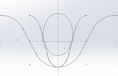
You've got three different views of a gear profile. I am not too involved with involutes but deal with straight flank thread profiles.
The axial view is taking a threaded rod and slicing it down the middle length wise, and looking at the flat portion.
The transverse axial view is looking down the rod from the end.
The normal view would be tilting the threaded rod to the helix angle and looking at the thread.
I guess before I get carried away to answer your original question, the helix is a function of how much travel to how much turn of the gear. your need.
I use tan^-1 (lead/(PI*pitch Dia.) to find my helix angle.
Think of it as a simple triangle.
The opposite side is your pitch the adjacent side is your pitch diameter (hence why involute gears can have varying leads because the minor diameter, pitch diameter, and outer diameter all have longer or shorter lengths) and the hypotenuse is your nut travel length. Also not to mention varying flank angles for constant engagement. The diagram below is opposite of what I mentioned.
Just remember pitch is lead/# starts so 1" lead on 1 starts is 1" pitch, 2 starts is .5 pitch.

Hope this helps and by all means I've never had to explain this to anyone so if anyone finds holes just reply back and I'll correct it.
I am still learning after 5 years of trial and error.
You've got three different views of a gear profile. I am not too involved with involutes but deal with straight flank thread profiles.
The axial view is taking a threaded rod and slicing it down the middle length wise, and looking at the flat portion.
The transverse axial view is looking down the rod from the end.
The normal view would be tilting the threaded rod to the helix angle and looking at the thread.
I guess before I get carried away to answer your original question, the helix is a function of how much travel to how much turn of the gear. your need.
I use tan^-1 (lead/(PI*pitch Dia.) to find my helix angle.
Think of it as a simple triangle.
The opposite side is your pitch the adjacent side is your pitch diameter (hence why involute gears can have varying leads because the minor diameter, pitch diameter, and outer diameter all have longer or shorter lengths) and the hypotenuse is your nut travel length. Also not to mention varying flank angles for constant engagement. The diagram below is opposite of what I mentioned.
Just remember pitch is lead/# starts so 1" lead on 1 starts is 1" pitch, 2 starts is .5 pitch.
Hope this helps and by all means I've never had to explain this to anyone so if anyone finds holes just reply back and I'll correct it.
I am still learning after 5 years of trial and error.
Attachments
Last edited:
- Joined
- Mar 22, 2013
- Messages
- 215
To actually answer your question I would say it's using a machine with a tool to cut a groove around a cylinder in the shape of a spring. The helix angle would be how far apart the coils on the spring are. The wider they are the greater the helical angle.
A gentleman on one of the other model engineering forums (Chuck Fellows) (deceased) designed a fixture for the home machinist to be able to cut helical gears. In the thread he posted information sheets on how to develop the templates to cut a helix using the fixture and calculations. Having cut many of my spur gears over the years I was taken in with the information and built the described fixture. In using it one has to make a template for each gear. The template coincides with the diameter of the gears blank the diametral pitch of the gear and the angle of the helix. Not having a great selection of D.P. involute gear cutters I regularly make make my own. (Another story) Since cutting my first helical gear I really enjoy making them for my engines that can use them.
To answer the second part of your question, I'm assuming that you referred to the procedure of hobbing. Hobbing is the process of setting up a gear hobbing mahine to first rotate the gear blank and second rotate the hob so that it rotates at the proper speed to cut the desired D.P. or Module of the gear. The hob has teeth cut into it that are helical in form. Meaning that the hob is like a tap. If you mounted a tap into a spindle (lathe) and ran it against a piece of metal (stationary) the teeth of the tap would cut a groove into the metal equal to the outside diameter of the tap. Now if you fed that tap into the metal at a rate equaling the pitch of the tap you would get threads. In the hobbing machine the gear blank is rotated to match the lead of the cutter and presto, you get a gear. To cut helical gears the gear blank is rotated at an angle to match the desired helical angle and the gear train is set up to synchronize the roational speed of the gear blank to the lead on the cutter. The same as cutting a spur gear but with the helical angle thrown in. The nice thing about using a gear cutting hob and a gear hobbing machine is that you only need one hob per D.P. or Module. Whereas cutting a gear with an involute cutter requires having a set of 8 cutters to cut the full range of teeth. As a gear gets larger and has more teeth the profile of the teeth change hence the need for multiple cutters.