HELP! Compressor Pipe Questions

Just a little side note, oem compressor companies use tubing for several reasons, one of them is they aren't so rigid as hard pipe so they can tolerate more vibration, another reason besides reduced installation costs is this piping gets pretty hot, it expands and contracts with the heat, any material does. The tubing can tolerate the growing and shrinking better than a more rigid material.
I like your idea of going to some sort of heat exchanger before going into the tank, add a drop on the outlet side to catch condensation
 
On second thought...
I set my compressor up almost 4 years ago and forgot that the check valve from the tank will not fit in the cooler, it's too long.
I used one of these, https://www.portlandcompressor.com/store/34-x-34-genie-check-valve

If you don't want to spend the money you can wait and see if you have an issue. I often use mine with a 3/4 hose at full tank pressure (175psi) for some oddball stuff and had some hard starts.
 
I forgot about the difference between pipe and tube measurements. Yes, the compression fittings on both ends of the pipe are straight. The fitting at the tank is 3/4" NPT male into the tank and female on the other end. This fitting has the 1/4" tube threaded into it for the pressure regulator. The elbow that attached to it was 3/4" NPT on the tank side and straight thread on the other, so I simply removed it and can use standard NPT from there.

I can weld aluminum, but I'm bad at it. I think I'm better off making a new part. Drill America sells a 3/4" NPT tap and drill for $15.25, delivered. I'm leaning toward this. I want the compression business out of there and to stick with NPT, otherwise lots of adapting. I'm going to look it over again today and think about everyone's posts.

I appreciate everyone's input.

I found a good way to remember the difference between straight threads and tapered NPT threads is to build a filter for a 180gal aquarium and spend months slopping up the dribbles until you realize the difference between straight threads and tapered threads. ;)

I think building a new part is a good idea... I mainly wanted to bring my hard learned lesson to your attention.

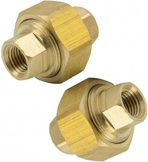
Usually the purpose of a compression fitting instead of a NPT fitting is a compression fitting allows you to tighten and seal the joint without having to turn the pipe. To do the same with NPT fittings you need to use a union which sandwiches a compression fitting between two NPT fittings.

61UdKbd8qfL._AC_UF894,1000_QL80_.jpg

My gut instinct is that the fitting on the pump should remain a compression fitting.

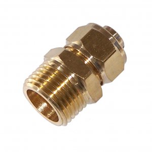
They do make NPT to compression fittings:
51212.jpg
 
Last edited:
Hi everyone,
I appreciate your recommendations, education, and patience, for that matter, and I want more, please. This is my setup and plan.
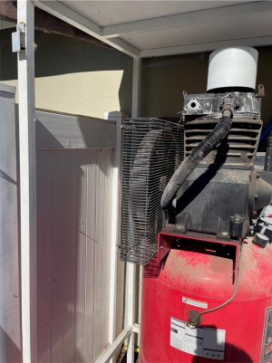
Plan for Aftercooler.jpg
This is a partial view of the compressor closet on the side of my garage. Two sides consist of the garage wall, and one is the 6’ vinyl fence facing the street (in the photo). The other two sides are matching vinyl siding panels that are set into U-shaped brackets. The top brackets swivel on bolts, making access to the compressor from the two important sides quick and easy. The bottom of these panels sit about 6” above the concrete. I extended the tank drain and ball valve to be flush with the panel so it’s protected and easy to get to without having to lie down to get to it. For those who read the Today’s Joke thread—It counts as a squat!

I live in an association and did not seek approval before I built it, but I built it to be stealthy and figured it would be better to ask forgiveness than permission. I painted the steel white to match the fence and house trim, and the roof matches the house. I got away with it for two years before they noticed. Fortunately, all I had to do was to submit an application, and they approved it.

My plan is to mount the aftercooler and water separator with auto drain between the two uprights on the left in the photo. I will run it without a cooling fan, but I will add one if needed. My two high-air volume requirements are for the blast cabinet and the plasma cutter. I intend to do some painting soon.

I can make a new flange for the head and either use copper tubing or the leftover 3/4” RapidAir tubing to and from the aftercooler. Is one more appropriate than the other? Both would use compression fittings. There is plenty of material in the head for me to tap and thread, as @sdelivery suggested. Drill America, via Amazon Prime, sells a drill and tap for $15.25 delivered. I am hesitant to modify the head.

Note the fitting in the tank with the 1/4" line extending up to the regulator. @Firstram, is this simply a fitting, or is there a check valve in it? Do I leave it, move it, or what? I'm trying to wrap my mind around this piece and the Genie check valve you recommend. I like the idea, and the price is reasonable. The photo below shows a valve, but I'm not sure it does what the check valve you recommend does. I'm not sure if they are the same thing or if both are necessary. I always hear a valve relieve pressure, but I've never noticed which one is doing it.
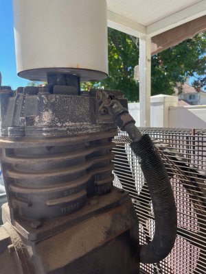
IMG_3844.jpg

This is all I can think of for now. Thanks!
 
The last picture shows an overpressure pop-off valve. If there is too much pressure, it opens up (via a spring mechanism, I think) and relieves the pressure. You can pull on that ring to activate it if you want to scare the crap out of yourself. Once you let go (which you will quickly due to the noise) it will shut itself off.

The check valve the guys are referencing is usually located in the inlet port of the tank. It would also have a small pressure line that trips the pressure switch to stop and start your compressor. It looks like it might be located on the side of your tank, according to the first picture in your above post.

Also, it should be noted that most. fittings and tubing on a compressor are based on HVAC standards. The copper fittings for example are ACR (air conditioning refrigeration). FTG means that the fitting is the same size as the pipe. If it has a "x c", that signifies that a cup will fit over it, or a piece of pipe, therefore eliminating the need for a reducer. Clear as mud. I probably got something wrong in there but just be aware that a copper fitting in the local hardware store will generally not work on copper tubing or HVAC stuff, such as air conditioner coils.


I want to add an "A-coil" to my compressor for air drying purposes.
 
A better picture would help but it looks as though this is a two stage pump, between the stages it runs through an heat exchanger cooled by the pumps flywheel integeral fan.
The check valves blocks the air from returning to the pump.
The small line that runs from the check valve to the pressure switch is the unloader bleed line.
When the pressure switch reaches the pressure the switch is set for it stops the motor and vents the pressure in the outlet line.
Reciprocating compressors use Reed valves and require 0 pressure to seat.
 
Personally, I would not attempt to tap the head with pipe threads. You only get one chance to not ruin it and a 3/4NPT tap into unknown aluminum alloy is asking for trouble, especially a cheap tap! That should be reserved for a last attempt to save a damaged head!!

I suggested you fab a new manifold using a pipe fitting because it's really cheap and easy, and NPT to compression fittings are readily available. The line from the compressor to the cooler needs to withstand vibration and should be copper or braided high temperature hose. A rigid connection will break something!

The fitting in the side of the tank is a check valve that maintains tank pressure and allows the head to bleed down. Since the bleed down happens through a 1/8" ID copper line, it's sort of slow. When you add in the air volume of that big cooler and a water trap, it take 3-4x as long. I ran into hard starts during heavy use when it tries to cycle quickly. Unfortunately, that style of valve is very long and will not thread into the cooler.

I needed to add the valve I linked earlier to stop the cooler from bleeding down for faster reset times. It may not be necessary for you, get it running and use it. You can time the bleed down hiss, then time the compressor off time during your heaviest use. Bleed down time should be less than or equal to off time.

The valve I linked is NPT to compression and can be swapped in with minimal effort at any time!
 
The valve I linked is flow actuated and self bleeding, no copper tubing needed. If you do add one. you'll want to remove the 1/4" tube and plug the hole in the tank check valve.
 
The valve I linked is flow actuated and self bleeding, no copper tubing needed. If you do add one. you'll want to remove the 1/4" tube and plug the hole in the tank check valve.
Thank you! I think I have a good handle on how to proceed. I post the finished product in the next week or so.
 
I can make a new flange for the head and either use copper tubing or the leftover 3/4” RapidAir tubing to and from the aftercooler. Is one more appropriate than the other? Both would use compression fittings. There is plenty of material in the head for me to tap and thread, as @sdelivery suggested. Drill America, via Amazon Prime, sells a drill and tap for $15.25 delivered. I am hesitant to modify the head.
I know the rapid air tubing would be tempting to use but due to the high heat and high vibrations I think you would be best with the copper tubing. I replaced the tank on an old 3 cylinder single stage compressor and used heavy high pressure fuel line hose rated for 1000psi with JIC barbs between the pump and the new tank and it eventually blew apart. I went back to copper tubing and it has been fine for a decade or so now.

Just a suggestion.
 
Back
Top