Help with cutting a 41 tooth gear blank

jlmanatee

Registered
Registered
Joined
Dec 29, 2014
Messages
43
On my mill I want to prep a 41 tooth gear blank for hobbing a worm wheel. My rotary table has a 72:1 driving ratio. My only available dividing plate has hole patterns of 15, 21, 28 and 34. Is this even possible with my particular rotary table and dividing plate? Or do I have to make a one-off dividing plate with holes spaced for a 72/41 ratio? Since 41 is a prime I assume..... I don't know what to assume. I have a headache now. Help!
 
Last edited:
Not owning a mill or rotary table I have to cut my gears in a different fashion.
check this thread https://www.hobby-machinist.com/threads/tumbler-reverse.10122/
for post 14 for the idea, post 21 for the assembly and where to get the index wheel, post 26 for the cutting.
I checked the gear index print and it works for 41 teeth if you make the elements the same at 41.
I used a hand ground profile single point cutter but if you have a real profiled gear cutter that would be better.
 
Depends on the application. If you're trying to recreate a broken or worn part, you may be opening the proverbial can of worms with meshing issues. If you have freedom of design, then design for what you can make.

What are you trying to achieve? Out of interest, if nothing else :)
 
In another thread, pertaining to my Grizzly G4000 lathe, I've had endless problems with grinding this gear to dust in maybe 2-3 three passes of my carriage power feed. The gear replacements I've gotten from Grizzly are sintered powdered metal (I think). I was hoping to make a 41T gear from better material.
 
Last edited:
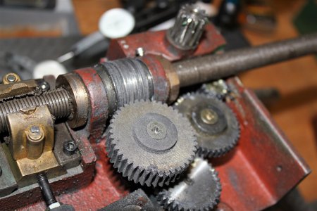
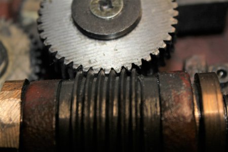
Ah, just read your thread. You mentioned that the mesh wasn't good with the worm gear? If that's still the case you may find that a 42 tooth wheel actually helps this somewhat.

Having said that, finding the cause of the actual problem is probably more productive than making a stronger gear.... You may just end up breaking something else. Powder metal gears survive perfectly well in all sorts of applications such as angle grinder gearboxes and suchlike, so trundling away in an apron shouldn't be an issue all other things being equal! It's not an easy task to produce a proper worm wheel either.

A few things spring to mind here to look at:

Is something binding and causing excessive load on the gear?

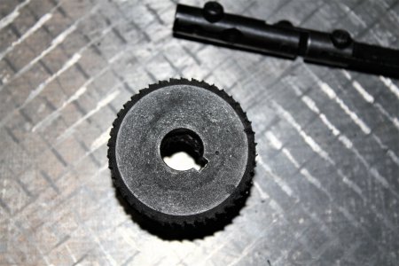
Is the worm gear tooth profile misformed in any way and actually cutting the wheel?

Is something misaligned causing the mesh to be poor?

Is the mesh still poor even with your mod to hold the gear more positively in the apron? How much backlash is there?

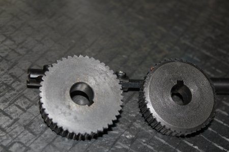
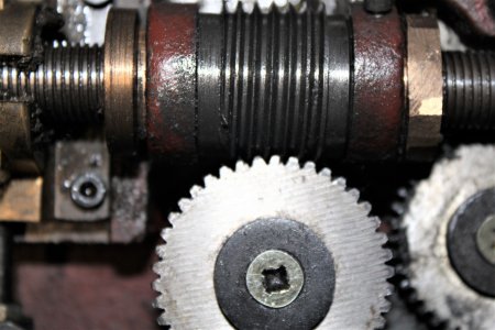
Some pics would help no end :) for a gear to get destroyed so quickly, something other than the gear is definitely not right!
 
Some pics of my "grinder"
 

Attachments

  • 41T_grind.JPG
    41T_grind.JPG
    854.5 KB · Views: 23
  • 41T_grind2.JPG
    41T_grind2.JPG
    797.4 KB · Views: 26
  • IMG_1399.JPG
    IMG_1399.JPG
    878.6 KB · Views: 26
two more images.
 

Attachments

  • 41T_grind3.JPG
    41T_grind3.JPG
    617.7 KB · Views: 26
  • 41T_grind4.JPG
    41T_grind4.JPG
    749.3 KB · Views: 22
That worm wheel looks very worn and the meshing very tight despite the wear. Judging by the tooth profile on the wheel I'd say the worn worm is a big factor here.
That being said, I wonder if this is just a nasty cheap design... Are the teeth on the wheel angled to mesh with the gear correctly? If not, was the slop fit you fixed really to let the gear settle to an angle where it cludges itself into some kind of mesh with the straight cut teeth?

Either way, that worm gear needs replacing. What I'd do, if I may? Cut a 40 tooth wheel using the gash and hobb method, along with a new worm gear of a diameter which with give you a good mesh:

 
Back
Top