I want to bore an aluminum 40 tooth T5 pulley for a much larger shaft.
I'm replacing the gear on the spindle that normally drives the change gears for my PM-1130v lathe. In place of the change gears, I now have an encoder for an Electronic Lead Screw (ELS). The encoder is driven by a T5 timing belt so the spindle gear needs to match T5 timing belts.. Currently, I have a 3d printed gear in place that probably would work long term. But, I'd already ordered an aluminum pulley and would like to make it fit.
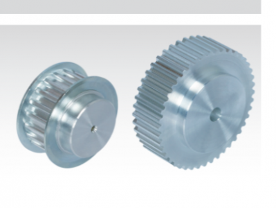
The gear I've ordered is from Maedler. It's a 16224000. Looks like this:

I plan to pry/press/hammer the flanges off, so it should end up like the one to the right in the picture. The pulley OD is 62.82 mm. It comes with an 8mm bore...which is just a tad smaller than the 48 mm bore that I need. I think in the above picture, the bore is about the size of the visible hub. So almost everything except the toothed area is going to be removed.
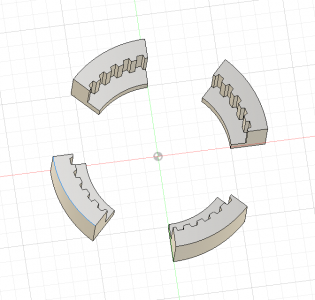
To cut this on a lathe, I was thinking about 3d printing the pieces shown below. The teeth and the dimensions will match the pulley. I've got 5mm of plastic "behind" the pulley so that there's space to do the bore w/o cutting into the 4-jaw chuck jaws.
I have all the expertise of someone who is just starting at this. Does this seem like a reasonable approach for workholding? The lathe seems to be the appropriate tool for the job, but I do have a CNC mill (a printNC) and I probably could mill the bore area.

I'm replacing the gear on the spindle that normally drives the change gears for my PM-1130v lathe. In place of the change gears, I now have an encoder for an Electronic Lead Screw (ELS). The encoder is driven by a T5 timing belt so the spindle gear needs to match T5 timing belts.. Currently, I have a 3d printed gear in place that probably would work long term. But, I'd already ordered an aluminum pulley and would like to make it fit.
The gear I've ordered is from Maedler. It's a 16224000. Looks like this:

I plan to pry/press/hammer the flanges off, so it should end up like the one to the right in the picture. The pulley OD is 62.82 mm. It comes with an 8mm bore...which is just a tad smaller than the 48 mm bore that I need.
To cut this on a lathe, I was thinking about 3d printing the pieces shown below. The teeth and the dimensions will match the pulley. I've got 5mm of plastic "behind" the pulley so that there's space to do the bore w/o cutting into the 4-jaw chuck jaws.
I have all the expertise of someone who is just starting at this. Does this seem like a reasonable approach for workholding? The lathe seems to be the appropriate tool for the job, but I do have a CNC mill (a printNC) and I probably could mill the bore area.


