How do I remove the headstop in the ram casing?

Pauldarby1

Active User
Registered
Joined
Aug 26, 2013
Messages
35
I,m stripping the ram casing down and want to remove the head stop bracket. I've removed the top head stop bracket, which has a grub screw securing it. However the lower one doesn't appear to have a grub screw. I'm reluctant to just turn it with an adjustable spanner until I have consulted the forum. The parts diagram doesn't help much.
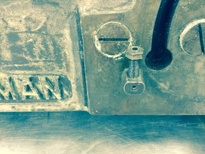
image.jpg
 
I tried to remove mine by unscrewing it but couldn't get it to budge so I ended up leaving them on and just cleaning around them

I noticed youre machine has 2 large flat head screws on the machined surface, what are they for? is yours one of the older models or newer? mine has a vague stained circle where the left screw is on yours, but no screw.

Todd
 
Mine was built during 1946.

The 2 large discs are threaded and access the gear shafts.

Paul
 
Re: How do I remove the headstop in the ram casing? (Van Norman No. 12)

I,m stripping the ram casing down and want to remove the head stop bracket. I've removed the top head stop bracket, which has a grub screw securing it. However the lower one doesn't appear to have a grub screw. I'm reluctant to just turn it with an adjustable spanner until I have consulted the forum. The parts diagram doesn't help much.
Hi Paul,

The head stop is part number 12-524 and as best I can tell from the parts diagrams, was used on all models of the No. 12 miller and on the No. 16 as well. The one you removed is that same part as the one that's still in the head. I assume that they are a press fit. I don't think that turning it with a spanner is going to do any good; you would probably have to use a slide-hammer to remove it.

Can you post a photo of the one you removed and the location of the grub screw hole in the head?

Out of curiosity, why do you want to remove it?

Cal
 
Cal,
thanks for the reply.ill post a picture in the next day or so. I am stripping the machine to have all surfaces re-ground and hand scaped. I wanted to remove it, to allow the machinist to be able to have unrestricted access to all the surfaces.

Paul
 
Cal,
thanks for the reply.ill post a picture in the next day or so. I am stripping the machine to have all surfaces re-ground and hand scaped. I wanted to remove it, to allow the machinist to be able to have unrestricted access to all the surfaces.

Paul
That makes sense. But make sure that the cutter-head and side of the ram actually need to be ground before you proceed. If you remove material you will change the mesh of the ring and pinion gear and will need to carefully set that up again when you reassemble. I would just spot the cutter-head to the ram and if they're bearing OK in both horizontal and vertical positions, leave them alone.

I don't know if you pulled the guts out of the cutter-head and ram gearbox yet, if you do, make sure that you put witness marks on everything so that the parts can go back in exactly the same potions. This applies especially to the ring gear in the cutter-head and the gearbox output shaft. You need to make some sort of gage to allow you to transfer the position of the right bearing socket (for lack of the correct term), part number 12-307, to the ram. The outer lock collar (12-337) and the right bearing outer race lock thingy (12-316) simply tighten against 12-307. For the ring gear, put witness marks on the (12-218) where the key is located and count the number of exposed threads on the spindle.

Cal
 
Cal,
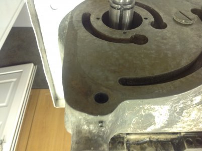
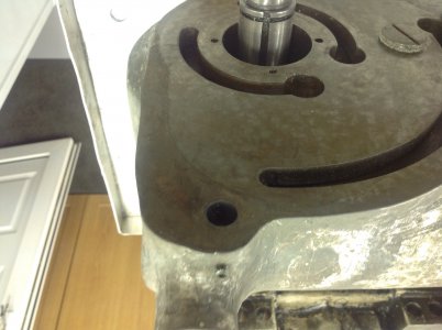
thanks for the advice. I really appreciate it. In the absence of a technical manual the advice is invaluable. Photo attached of grub screw location
.image.jpg

image.jpg image.jpg
 
Paul,

Thanks for the photo. Could you post a photo of the head stop? Is the shank round or tapered? Does it have a flat machined on it?

I can still see the original scraping marks on the ram. Unless the ram or cutter-head have warped over time, they probably don't need any work.

Cal
 
Cal,
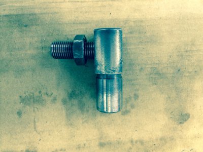
Photo of head stop attached. It's parallel and doesn't have a mmachined flat on it.

image.jpg
 
Cal,
Photo of head stop attached. It's parallel and doesn't have a mmachined flat on it.
Thanks Paul.

It must just be a press fit. You might compare the ID of the hole and the OD of the one you have out to see it that makes sense.

Does it appear to be hardened?

It doesn't look like they gave you anything to grab with a slide hammer; you'd probably mess up the threads on the stop adjuster if you tried to grab it by that. Rotating it back and forth a small amount to break it loose before trying to use the slide hammer is probably a good idea as is the use of penetrating oil.

Cal
 
Back
Top