- Joined
- Feb 5, 2015
- Messages
- 662
Those with more skill than me might resolve the problem differently than I did. Also please note that I'm focusing the discussion toward those who are less experienced, since this is a hobby forum.
Inexpensive drill chucks can't be "accurized" over their full range so I tried to optimize concentricity and axial alignment for my drill chucks at approximately 3/4 their diametric capacity. Using different capacity drill chucks near the middle of their adjustment range with quality twist drills (usually good screw machine drills) has produced good results for my modest requirements.)
Tolerance contributions prevent mass-produced drill chucks from achieving a high standard of accuracy. Consider how most drill chucks are assembled: the body of the chuck is either threaded or taper-reamed to accept an arbor. The shank of the arbor is configured for different machine tool applications, straight and tapered, depending on the machine to which the drill chuck/arbor is fitted. Obviously, internal details of keyed chucks are complex and production cost goals limit the ability to achieve concentricity over the full adjustment range.
Ignoring the internal mechanism, there are four critical interface configurations to get "right" so inexpensive products function as well as one might expect for the price. But it is possible to improve performance of some imported chucks significantly. The following is a description of a procedure I've used for some time - it has worked well for my personal drilling requirements. Note that this is intended for hobby machinists because they usually have available time and because there are several useful lessons to be learned.
This reads like a complicated process but implementation time should be two hours or less for a hobbyist. It is difficult to translate these ideas in written form - apologies if the explanations are unclear - hopefully photos can clarify the descriptions. We'll assume that your lathe is leveled, aligned, spindle bearings tight, no excessive wear - all the normal precautions. Experienced machinists can work around deficiencies in many of these areas but the rest of us should not assume that WE can.
Let's also make the presumption that the internal chuck mechanism has no inaccuracy. That may seem unfounded but it can be justified because the average home machinist has no capability to improve the internal details so we may as well ignore them. If one requires the best performance from a drill chuck, the price must be paid. (Many hobbyists don't require the performance of an expensive German-made drill chuck and that is the point of this post: attempting to achieve decent performance from inexpensive tools. For our purposes, let's assume that the greatest sources of error are external to the drill chuck.)
The greatest error contributor is usually the arbor/chuck interface - both parts are mass-produced to fit other mass-produced parts. Additional interfaces, arbor-to-spindle (or arbor to tailstock), introduce angular, concentric, dimensional and axial errors too but are partly compensable. The following assumes that we will be "accurizing" a lathe tailstock chuck, recalling that a presumption is that the lathe used to perform this work is properly aligned.
The premise is that we'll chuck and turn a reference pin in our lathe, so that it is as concentric with the spindle axis as the machine can produce. Without moving the reference, we will then secure the jaws of the chuck (that we want to true) over the pin. After performing preliminary and intermediate measurements/adjustments, we'll turn the drill chuck arbor concentric to the spindle, with the correct taper dimensions to fit the lathe tailstock.
Before commencing, it's necessary to purchase or make a blank arbor for the desired drill chuck. The arbor must mate securely with the drill chuck and have a shank diameter greater than that required for the eventual end use (if used in a Morse taper tailstock, the diameter must be greater than the maximum diameter of the tapered tailstock socket - with a little excess diameter and length). If your chuck has a MT-2 taper, for example, buy a MT-3 arbor so as to have excess material. If purchased, the blank arbor must be machinable (not hardened beyond around Rc-40 or so, softer if HSS tooling is to be used).
(A 2 MT shank drill chuck with excessive runout was available when I wrote this. I wanted the chuck to be useful and it was convenient for making photographs BUT it doesn't replicate the procedure that will be described. The procedure, please recall, was supposed to describe accurizing a tailstock chuck - but the example available to me had a diameter that was too small to convert it into a tailstock chuck. I actually turned the arbor to a straight 1/2 inch diameter for use in the vertical mill. Please keep in mind that the "accurizing" procedure doesn't reflect this and I'll try to point out divergences.
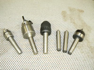
The next step is to select (or obtain) a tailstock tool that is well-fitted to the taper in your tailstock. This is important because it will become the reference for a critical part of the procedure. Most of us have several Morse taper centers and several Morse taper drill chucks for the tailstock; we can sort through them and select the best one (the drill chucks shown in the photo were trued using this technique).
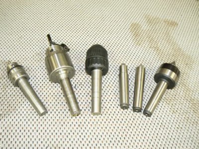
After thoroughly cleaning the tailstock socket, pick the tool with a taper that best fits your tailstock socket. There are various methods of inspection/comparison but an easy (and conventional one) is bluing the taper on the tool, inserting in the tailstock socket and maybe slightly rotating the seated tool. Inspecting the various tools, the one with the greatest area of contact (most bluing wiped off) is the tool that best fits your tailstock socket. In my case, this happened to be an after-market dead center, so I'll use that part and that taper to illustrate the following steps.
A finicky part of the turning process is aligning the lathe compound rest to replicate the taper of the tailstock. So before a lot of time is expended in the process (and although this might seem to be obvious) first confirm that the compound travel on your lathe is adequate to turn the full length of the tailstock taper. (Traditional European and American-made lathes always had this capability but some Asian imports do not.)
Commence the process by moving the tailstock near the headstock, in the position that will be required to support the arbor when it is trued. You won't know the exact location at this point but after reading a few more paragraphs, the location will become clearer. Place a DTI in the headstock workholder (chuck or collet, whichever is convenient), lock the tailstock to the ways and carefully sweep the tailstock socket for concentricity with the lathe spindle (a small mirror can be helpful to observe the DTI when it is rotated out of view). Make a preliminary alignment of the tailstock if necessary.
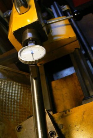
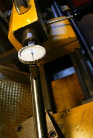
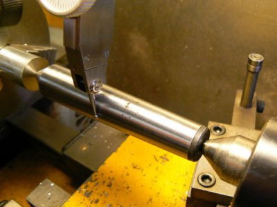
The simple tool shown above is convenient for situations like this one. It consists of an inexpensive .0005 DTI permanently mounted to an 18 inch length of 1/2 drill rod. (I use it often to check tailstock alignment before center drilling and to center the tailstock after adjusting for taper turning, for example.) I made a spread sheet that calculates the amount of sag depending on the stickout of the indicator.
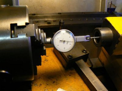
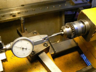
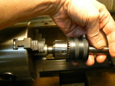
When working close to the headstock, often the DTI can be installed directly in chuck or collet like this:
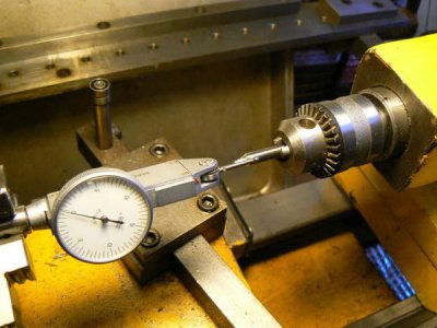
Next, install a drill chuck with center drill in the tailstock bore. Sweep the center drill body with the DTI and, if it is not coaxial with the spindle, select another center drill. If available center drills aren't concentric it may be possible to shim one in the drill chuck to reasonable concentricity. You may also try rotating the drill chuck in the tailstock until the least runout has been achieved.
Center drilling is an important step because the center that is used as a reference for the taper will be supported in the hole produced by this drill. Other irregularities in the center drill influence alignment of the workpiece but let's work with variables that we can cope with. (A better method, requiring slightly more time, is to bore the center hole in the workpiece, using the compound slide. This can be tricky for small center holes but is practical using a small, broken end mill or tap ground as a boring bar.)
A good habit to develop is to "load" moveable parts of metalworking machinery the same way each time movement is required. We know to take up backlash in lathe and milling machine hand-wheels in the same direction and the concept is universal, if we want to achieve consistent results (especially on older machines). If there is any play, any movement between parts, be sure to take up the movement in the same direction every time. In THIS case, when moving the tailstock from one position to another position, always push it against the same side of the ways before tightening the clamping nut UNLESS there is a wear characteristic that suggests a different practice. (The tailstock should be similarly loaded when it is aligned with the spindle centerline.)
OK, next step …
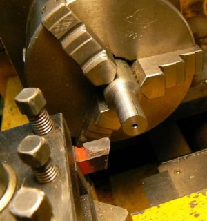
Chuck a steel rod SECURELY in the lathe workholder. The diameter should be greater than the maximum capacity of the chuck to be "accurized" (3/4 inch is about right for small drill chucks. Face the end of the steel rod and carefully center drill the piece. This is important - if there is any doubt about concentricity, use a small boring bar to true the "starting" hole and produce a center hole with the compound slide, as previously described.
Turn the steel rod in the headstock to a diameter that is approximately 3/4 the maximum capacity of the drill chuck to be accurized. The length of the turned diameter should be slightly more than the gripping length capacity of the drill chuck. Carefully measure the diameter of the workpiece at each end to confirm that there is no taper. If required, correct by draw-filing, sanding and so forth until the "pin" is as straight as measurement capability allows.
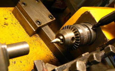
Incidentally, once you are satisfied with the tailstock alignment and the concentricity of the center drill, it's a good idea to be able to re-insert a center drill in the tailstock with some assurance of satisfactory alignment. Using an indelible marker, you can mark the drill chuck arbor and the tailstock ram so that the drill chuck/center drill can be removed and re-installed in the tailstock while in the same position.
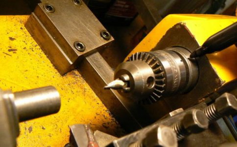
It is also good practice, once the center drill is well adjusted, to leave it permanently in the same chuck to which it is aligned for all future center drilling applications. Three chucks are useful for the lathe and for the milling machine: a 5/8 inch capacity keyed chuck, a 1/2 inch capacity keyless chuck and a 1/4 inch keyed chuck permanently loaded with center drill, properly aligned as above.
(It's surprising how convenient it is to have the ability to secure several different tools in available drill chucks, having them readily available for tailstock installation. Counterboring, step-drilling or countersinking on several parts is facilitated by removing and inserting various chucked tools in the tailstock rather than having to remove and re-insert tools in a single drill chuck.)
Remove the drill chuck from the tailstock and replace it with a known good center. Locate the "reference center" between the previously center drilled hole in the steel "pin" and the tailstock center. (Use the center previously blued and tested as the reference dead center.)
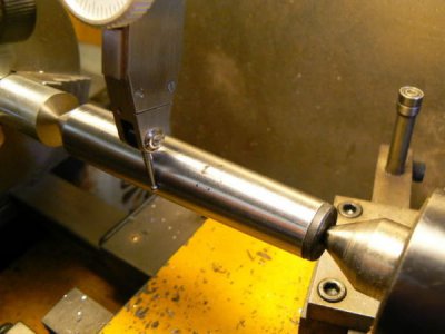
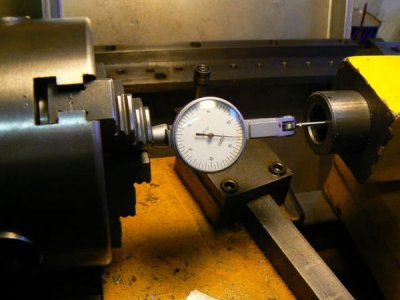
Loosen the compound locking nuts and rotate so that the compound slide is approximately parallel to the taper of the reference center. As shown above, install a DTI in the tool post (or use a magnetic base) and adjust the tip of the DTI on the exact centerline of the reference center – if in doubt, use the 6 inch machinists scale method to check. Lock the lathe carriage and traverse the compound slide while observing the DTI.
Make fine adjustments to the angle of the compound slide until the reference center can be swept over the full travel of the compound slide with no detectable error. The compound axis is now parallel with the taper of the reference center (within the limits of the DTI). Unlock the tailstock and back it away, removing the reference center. The reference center will not be required for the remainder of the process.
After thoroughly cleaning the interior of the drill chuck, slip the "to be accurized" chuck (fitted to the blank arbor that will be turned) over the reference diameter previously turned from the 3/4 diameter steel rod in the headstock chuck) and snug the jaws.
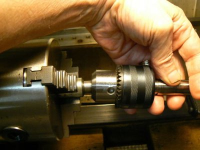
Rotating the drill chuck by hand over the reference diameter, tighten the chuck wrench gradually until the chuck is completely secured. Replace the tailstock chuck + center drill in the tailstock, using the alignment marks that were established before removing the chuck earlier. Carefully center drill the end of the blank drill chuck arbor then remove the drill chuck from the tailstock.
Install the "known good" tailstock center, lubricate it and adjust to apply moderate pressure to the center drilled hole in the drill chuck arbor.
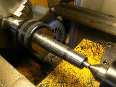
Let's understand what we have accomplished so far.
I decided to modify the drill chuck to fit my vertical mill by fitting to an R-8 arbor with 2 MT bore that I wasn't using. After truing the drill chuck arbor taper, the smaller diameter taper couldn't fit this arbor, just as it would not fit the lathe tailstock socket. BUT the R-8 holder could be modified to accommodate the smaller taper on the drill chuck … Clearly modifying the tailstock ram wasn't under consideration, ha-ha. We'll get to the R-8 modification shortly, it's really incidental to the purpose of this discussion.
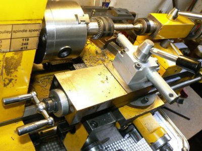
We want to minimize cutting tool overhang, especially for small lathes that aren't very rigid. In this setup configuration, the compound slide has to be as close as possible to the headstock - without interfering with rotation of the hand-wheel. Adjusting the cross-slide, so that the compound can obtain full travel without "bumping" the headstock with the hand-wheel, is not easy to accomplish on a small lathe.
Take a look at the next photo - notice how close the compound adjustment handles are to the headstock ! After adjusting the cross-slide for minimum interference, it will be apparent that the lathe tool post is further from the workpiece than we would like.
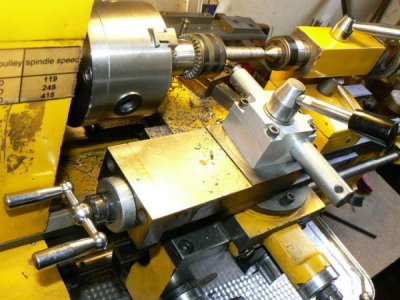
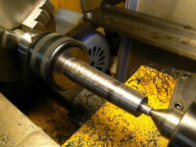
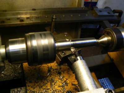
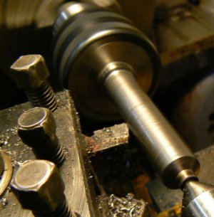
Improvisation is required to position a cutting tool close enough to the workpiece with sufficient rigidity to turn the taper on the blank arbor. We've all used makeshift setups to achieve workable solutions, right ? The simplest solution, in this case, was to use a boring bar as a turning tool. In the following photo the shop-made boring bar with a brazed-carbide tool is turning the taper.
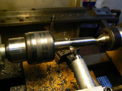
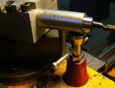
A practical expediency is to support the end of the cutting tool with a machinist's jack, shown in this photo. Note that the "vee" groove in the top of the jack is helpful for supporting round objects like a boring bar.
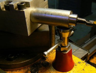
Cut the taper on the blank arbor until the desired diameter and fit is obtained. This can be determined by measuring the major diameter and - when the diameter is near finish size - checking the fit as follows: unlock and back off the tailstock, remove the center and slide the tailstock over the arbor and check for fit by bluing and rotating the arbor slightly in the tailstock. (Be careful to load the tailstock in the same manner as when it was originally moved up to support the workpiece.)
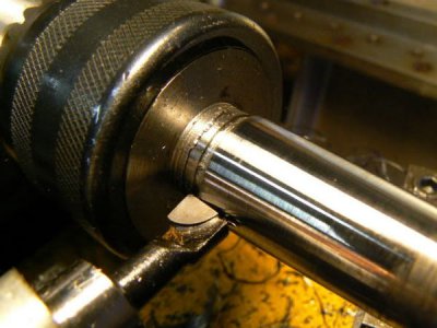
Once the desired fit has been obtained, lightly sand/steel-wool the arbor to a clean, smooth surface. In the following photo, an existing, semi-hard arbor has been re-trued. A good finish is required so that the tapers properly "lock-up" by friction.
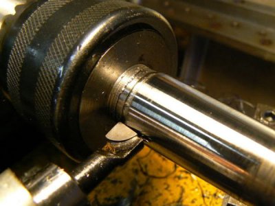
Returning to the small problem of modifying a 2 MT undersize arbor to fit an R-8 adaptor … we know that the modified taper is too small for the R-8 arbor. In order for the two parts to properly mate, the face of the R-8 arbor must be cut back until the socket diameter matches the large diameter of the drill chuck shank. In large lathes, this is a simple operation, chuck the R-8 workholder and face the front surface with a carbide cutting tool.
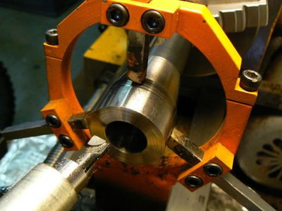
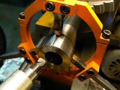
My smallest lathe doesn't have a large spindle bore so the operation was slightly more time consuming. Here's a photo, the untapered end of the R-8 adaptor is held in the 3-jaw headstock chuck of the lathe, supported at the front with a shop-made steady rest (FYI, note that the tips of the bearing surfaces have been "tinned" with bronze brazing rod, for a good bearing surface). The same carbide boring tool previously used to turn the drill chuck arbor was used for facing the adaptor (it was already in the setup).
For truing drill chucks with straight shanks used in milling machine collets or the 5/8 diameter shanks normally used in bed turrets, the procedure is simpler. No taper need be turned on the arbor although the tailstock center must still be used for support otherwise the arbor may disengage from the chuck. There are a few things to consider when making milling machine drill chuck arbors. A shank diameter of around 3/4 is desirable for reasons of rigidity, accuracy and wear. However one might also want to consider time expended in tool changes.
Most of my previous work involved making small parts and the largest R-8 collets got infrequent usage. I used two drill chucks frequently; one is 5/8 capacity attached to an R-8 arbor with .003 runout (at the chuck face) when purchased. That's OK for "Silver and Deming" type drills, for example, where maximum metal removal is the goal rather than precision. Small straight shank drill chucks usually can't handle heavy feeds required by these large drills, there's insufficient friction - they will often slip in a collet, possibly damaging both the arbor and the collet.
For greater precision (small diameter drills), a small chuck was "accurized" using the previous procedure. A straight shank diameter of 1/2 inch was chosen for the arbor. The reason for selecting this diameter was because most of my milling operations require a 1/2 inch collet so a collet change isn't required when switching from end mill to drill chuck.
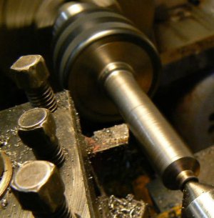
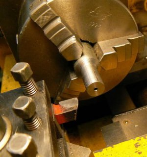
If one uses an older manual vertical mill, it's quicker to insert a drill chuck with a short, straight shank into a collet rather than cranking the knee down ten times to install the longer R-8 mounted chuck, then cranking it back up again to working height. Here's a drill chuck with shank being trued to a straight 1/2 diameter:
Arbor material shouldn't be harder than what can be readily worked with available carbide tooling - most of us have no precision grinding capability. This suggests that one might expect occasional "dings" on an unhardened arbor. This should not a problem provided that you are aware of the possibility. Make it routine practice to quickly run the taper through your fingers, feeling for irregularities before installing into tailstock or spindle. (If/when found, file/stone irregularities flush with the original surface.)
Of the four chucks in current use that have been trued with this procedure and measured after truing, all displayed less than .0005 runout, one inch away from the chuck jaws after performing this procedure. The measurement was made by indicating a ground pin, diameter approximately 1/2 the maximum chuck capacity, secured in the chuck jaws. (Wear on the mechanisms has doubtless degraded performance since that time.)
One last suggestion … before the compound angle is disturbed, make up three or four blanks with the "perfect" tailstock taper. Buy a MT adaptor that has an OD suiting your lathe headstock taper and ID to fit the tailstock taper. Installing your precisely-turned taper blanks into the adaptor and fitting the adaptor into the headstock taper, special tailstock tooling can be made up when required without having to repeat the compound angular alignment. (If the tapers can't be locked with a tailstock center, it may be necessary to drill/tap the small end of the taper for a drawbar, to hold the tapered workpiece securely for machining.)
Inexpensive drill chucks can't be "accurized" over their full range so I tried to optimize concentricity and axial alignment for my drill chucks at approximately 3/4 their diametric capacity. Using different capacity drill chucks near the middle of their adjustment range with quality twist drills (usually good screw machine drills) has produced good results for my modest requirements.)
Tolerance contributions prevent mass-produced drill chucks from achieving a high standard of accuracy. Consider how most drill chucks are assembled: the body of the chuck is either threaded or taper-reamed to accept an arbor. The shank of the arbor is configured for different machine tool applications, straight and tapered, depending on the machine to which the drill chuck/arbor is fitted. Obviously, internal details of keyed chucks are complex and production cost goals limit the ability to achieve concentricity over the full adjustment range.
Ignoring the internal mechanism, there are four critical interface configurations to get "right" so inexpensive products function as well as one might expect for the price. But it is possible to improve performance of some imported chucks significantly. The following is a description of a procedure I've used for some time - it has worked well for my personal drilling requirements. Note that this is intended for hobby machinists because they usually have available time and because there are several useful lessons to be learned.
This reads like a complicated process but implementation time should be two hours or less for a hobbyist. It is difficult to translate these ideas in written form - apologies if the explanations are unclear - hopefully photos can clarify the descriptions. We'll assume that your lathe is leveled, aligned, spindle bearings tight, no excessive wear - all the normal precautions. Experienced machinists can work around deficiencies in many of these areas but the rest of us should not assume that WE can.
Let's also make the presumption that the internal chuck mechanism has no inaccuracy. That may seem unfounded but it can be justified because the average home machinist has no capability to improve the internal details so we may as well ignore them. If one requires the best performance from a drill chuck, the price must be paid. (Many hobbyists don't require the performance of an expensive German-made drill chuck and that is the point of this post: attempting to achieve decent performance from inexpensive tools. For our purposes, let's assume that the greatest sources of error are external to the drill chuck.)
The greatest error contributor is usually the arbor/chuck interface - both parts are mass-produced to fit other mass-produced parts. Additional interfaces, arbor-to-spindle (or arbor to tailstock), introduce angular, concentric, dimensional and axial errors too but are partly compensable. The following assumes that we will be "accurizing" a lathe tailstock chuck, recalling that a presumption is that the lathe used to perform this work is properly aligned.
The premise is that we'll chuck and turn a reference pin in our lathe, so that it is as concentric with the spindle axis as the machine can produce. Without moving the reference, we will then secure the jaws of the chuck (that we want to true) over the pin. After performing preliminary and intermediate measurements/adjustments, we'll turn the drill chuck arbor concentric to the spindle, with the correct taper dimensions to fit the lathe tailstock.
Before commencing, it's necessary to purchase or make a blank arbor for the desired drill chuck. The arbor must mate securely with the drill chuck and have a shank diameter greater than that required for the eventual end use (if used in a Morse taper tailstock, the diameter must be greater than the maximum diameter of the tapered tailstock socket - with a little excess diameter and length). If your chuck has a MT-2 taper, for example, buy a MT-3 arbor so as to have excess material. If purchased, the blank arbor must be machinable (not hardened beyond around Rc-40 or so, softer if HSS tooling is to be used).
(A 2 MT shank drill chuck with excessive runout was available when I wrote this. I wanted the chuck to be useful and it was convenient for making photographs BUT it doesn't replicate the procedure that will be described. The procedure, please recall, was supposed to describe accurizing a tailstock chuck - but the example available to me had a diameter that was too small to convert it into a tailstock chuck. I actually turned the arbor to a straight 1/2 inch diameter for use in the vertical mill. Please keep in mind that the "accurizing" procedure doesn't reflect this and I'll try to point out divergences.
The next step is to select (or obtain) a tailstock tool that is well-fitted to the taper in your tailstock. This is important because it will become the reference for a critical part of the procedure. Most of us have several Morse taper centers and several Morse taper drill chucks for the tailstock; we can sort through them and select the best one (the drill chucks shown in the photo were trued using this technique).

After thoroughly cleaning the tailstock socket, pick the tool with a taper that best fits your tailstock socket. There are various methods of inspection/comparison but an easy (and conventional one) is bluing the taper on the tool, inserting in the tailstock socket and maybe slightly rotating the seated tool. Inspecting the various tools, the one with the greatest area of contact (most bluing wiped off) is the tool that best fits your tailstock socket. In my case, this happened to be an after-market dead center, so I'll use that part and that taper to illustrate the following steps.
A finicky part of the turning process is aligning the lathe compound rest to replicate the taper of the tailstock. So before a lot of time is expended in the process (and although this might seem to be obvious) first confirm that the compound travel on your lathe is adequate to turn the full length of the tailstock taper. (Traditional European and American-made lathes always had this capability but some Asian imports do not.)
Commence the process by moving the tailstock near the headstock, in the position that will be required to support the arbor when it is trued. You won't know the exact location at this point but after reading a few more paragraphs, the location will become clearer. Place a DTI in the headstock workholder (chuck or collet, whichever is convenient), lock the tailstock to the ways and carefully sweep the tailstock socket for concentricity with the lathe spindle (a small mirror can be helpful to observe the DTI when it is rotated out of view). Make a preliminary alignment of the tailstock if necessary.

The simple tool shown above is convenient for situations like this one. It consists of an inexpensive .0005 DTI permanently mounted to an 18 inch length of 1/2 drill rod. (I use it often to check tailstock alignment before center drilling and to center the tailstock after adjusting for taper turning, for example.) I made a spread sheet that calculates the amount of sag depending on the stickout of the indicator.
When working close to the headstock, often the DTI can be installed directly in chuck or collet like this:

Next, install a drill chuck with center drill in the tailstock bore. Sweep the center drill body with the DTI and, if it is not coaxial with the spindle, select another center drill. If available center drills aren't concentric it may be possible to shim one in the drill chuck to reasonable concentricity. You may also try rotating the drill chuck in the tailstock until the least runout has been achieved.
Center drilling is an important step because the center that is used as a reference for the taper will be supported in the hole produced by this drill. Other irregularities in the center drill influence alignment of the workpiece but let's work with variables that we can cope with. (A better method, requiring slightly more time, is to bore the center hole in the workpiece, using the compound slide. This can be tricky for small center holes but is practical using a small, broken end mill or tap ground as a boring bar.)

A good habit to develop is to "load" moveable parts of metalworking machinery the same way each time movement is required. We know to take up backlash in lathe and milling machine hand-wheels in the same direction and the concept is universal, if we want to achieve consistent results (especially on older machines). If there is any play, any movement between parts, be sure to take up the movement in the same direction every time. In THIS case, when moving the tailstock from one position to another position, always push it against the same side of the ways before tightening the clamping nut UNLESS there is a wear characteristic that suggests a different practice. (The tailstock should be similarly loaded when it is aligned with the spindle centerline.)
OK, next step …
Chuck a steel rod SECURELY in the lathe workholder. The diameter should be greater than the maximum capacity of the chuck to be "accurized" (3/4 inch is about right for small drill chucks. Face the end of the steel rod and carefully center drill the piece. This is important - if there is any doubt about concentricity, use a small boring bar to true the "starting" hole and produce a center hole with the compound slide, as previously described.
Turn the steel rod in the headstock to a diameter that is approximately 3/4 the maximum capacity of the drill chuck to be accurized. The length of the turned diameter should be slightly more than the gripping length capacity of the drill chuck. Carefully measure the diameter of the workpiece at each end to confirm that there is no taper. If required, correct by draw-filing, sanding and so forth until the "pin" is as straight as measurement capability allows.

Incidentally, once you are satisfied with the tailstock alignment and the concentricity of the center drill, it's a good idea to be able to re-insert a center drill in the tailstock with some assurance of satisfactory alignment. Using an indelible marker, you can mark the drill chuck arbor and the tailstock ram so that the drill chuck/center drill can be removed and re-installed in the tailstock while in the same position.

It is also good practice, once the center drill is well adjusted, to leave it permanently in the same chuck to which it is aligned for all future center drilling applications. Three chucks are useful for the lathe and for the milling machine: a 5/8 inch capacity keyed chuck, a 1/2 inch capacity keyless chuck and a 1/4 inch keyed chuck permanently loaded with center drill, properly aligned as above.
(It's surprising how convenient it is to have the ability to secure several different tools in available drill chucks, having them readily available for tailstock installation. Counterboring, step-drilling or countersinking on several parts is facilitated by removing and inserting various chucked tools in the tailstock rather than having to remove and re-insert tools in a single drill chuck.)
Remove the drill chuck from the tailstock and replace it with a known good center. Locate the "reference center" between the previously center drilled hole in the steel "pin" and the tailstock center. (Use the center previously blued and tested as the reference dead center.)

Loosen the compound locking nuts and rotate so that the compound slide is approximately parallel to the taper of the reference center. As shown above, install a DTI in the tool post (or use a magnetic base) and adjust the tip of the DTI on the exact centerline of the reference center – if in doubt, use the 6 inch machinists scale method to check. Lock the lathe carriage and traverse the compound slide while observing the DTI.
Make fine adjustments to the angle of the compound slide until the reference center can be swept over the full travel of the compound slide with no detectable error. The compound axis is now parallel with the taper of the reference center (within the limits of the DTI). Unlock the tailstock and back it away, removing the reference center. The reference center will not be required for the remainder of the process.
After thoroughly cleaning the interior of the drill chuck, slip the "to be accurized" chuck (fitted to the blank arbor that will be turned) over the reference diameter previously turned from the 3/4 diameter steel rod in the headstock chuck) and snug the jaws.

Rotating the drill chuck by hand over the reference diameter, tighten the chuck wrench gradually until the chuck is completely secured. Replace the tailstock chuck + center drill in the tailstock, using the alignment marks that were established before removing the chuck earlier. Carefully center drill the end of the blank drill chuck arbor then remove the drill chuck from the tailstock.
Install the "known good" tailstock center, lubricate it and adjust to apply moderate pressure to the center drilled hole in the drill chuck arbor.

Let's understand what we have accomplished so far.
- We've established a reference diameter in the headstock that has been turned concentric to the lathe spindle.
- We've securely installed the chuck to be "accurized" on the reference diameter and accurately established a center at the end of the arbor. (Well, at least we've done these things within the limits of our machinery and our personal abilities, right ?)
- The drill chuck jaws are now aligned with the spindle axis and the center on the end of the arbor is on the lathe spindle center line.
- At this point, it is extremely unlikely that the blank drill chuck arbor is concentric with the spindle or parallel with the spindle center line and this is what we are going to correct.
- We've adjusted the angle of the compound as close as we can establish to the reference taper.
- All that remains is to taper the drill chuck arbor to the desired angle and diameter. Sounds simple but there may be a hiccup or two in store for us.
I decided to modify the drill chuck to fit my vertical mill by fitting to an R-8 arbor with 2 MT bore that I wasn't using. After truing the drill chuck arbor taper, the smaller diameter taper couldn't fit this arbor, just as it would not fit the lathe tailstock socket. BUT the R-8 holder could be modified to accommodate the smaller taper on the drill chuck … Clearly modifying the tailstock ram wasn't under consideration, ha-ha. We'll get to the R-8 modification shortly, it's really incidental to the purpose of this discussion.
We want to minimize cutting tool overhang, especially for small lathes that aren't very rigid. In this setup configuration, the compound slide has to be as close as possible to the headstock - without interfering with rotation of the hand-wheel. Adjusting the cross-slide, so that the compound can obtain full travel without "bumping" the headstock with the hand-wheel, is not easy to accomplish on a small lathe.
Take a look at the next photo - notice how close the compound adjustment handles are to the headstock ! After adjusting the cross-slide for minimum interference, it will be apparent that the lathe tool post is further from the workpiece than we would like.

Improvisation is required to position a cutting tool close enough to the workpiece with sufficient rigidity to turn the taper on the blank arbor. We've all used makeshift setups to achieve workable solutions, right ? The simplest solution, in this case, was to use a boring bar as a turning tool. In the following photo the shop-made boring bar with a brazed-carbide tool is turning the taper.

A practical expediency is to support the end of the cutting tool with a machinist's jack, shown in this photo. Note that the "vee" groove in the top of the jack is helpful for supporting round objects like a boring bar.

Cut the taper on the blank arbor until the desired diameter and fit is obtained. This can be determined by measuring the major diameter and - when the diameter is near finish size - checking the fit as follows: unlock and back off the tailstock, remove the center and slide the tailstock over the arbor and check for fit by bluing and rotating the arbor slightly in the tailstock. (Be careful to load the tailstock in the same manner as when it was originally moved up to support the workpiece.)
Once the desired fit has been obtained, lightly sand/steel-wool the arbor to a clean, smooth surface. In the following photo, an existing, semi-hard arbor has been re-trued. A good finish is required so that the tapers properly "lock-up" by friction.

Returning to the small problem of modifying a 2 MT undersize arbor to fit an R-8 adaptor … we know that the modified taper is too small for the R-8 arbor. In order for the two parts to properly mate, the face of the R-8 arbor must be cut back until the socket diameter matches the large diameter of the drill chuck shank. In large lathes, this is a simple operation, chuck the R-8 workholder and face the front surface with a carbide cutting tool.
My smallest lathe doesn't have a large spindle bore so the operation was slightly more time consuming. Here's a photo, the untapered end of the R-8 adaptor is held in the 3-jaw headstock chuck of the lathe, supported at the front with a shop-made steady rest (FYI, note that the tips of the bearing surfaces have been "tinned" with bronze brazing rod, for a good bearing surface). The same carbide boring tool previously used to turn the drill chuck arbor was used for facing the adaptor (it was already in the setup).

For truing drill chucks with straight shanks used in milling machine collets or the 5/8 diameter shanks normally used in bed turrets, the procedure is simpler. No taper need be turned on the arbor although the tailstock center must still be used for support otherwise the arbor may disengage from the chuck. There are a few things to consider when making milling machine drill chuck arbors. A shank diameter of around 3/4 is desirable for reasons of rigidity, accuracy and wear. However one might also want to consider time expended in tool changes.
Most of my previous work involved making small parts and the largest R-8 collets got infrequent usage. I used two drill chucks frequently; one is 5/8 capacity attached to an R-8 arbor with .003 runout (at the chuck face) when purchased. That's OK for "Silver and Deming" type drills, for example, where maximum metal removal is the goal rather than precision. Small straight shank drill chucks usually can't handle heavy feeds required by these large drills, there's insufficient friction - they will often slip in a collet, possibly damaging both the arbor and the collet.
For greater precision (small diameter drills), a small chuck was "accurized" using the previous procedure. A straight shank diameter of 1/2 inch was chosen for the arbor. The reason for selecting this diameter was because most of my milling operations require a 1/2 inch collet so a collet change isn't required when switching from end mill to drill chuck.
If one uses an older manual vertical mill, it's quicker to insert a drill chuck with a short, straight shank into a collet rather than cranking the knee down ten times to install the longer R-8 mounted chuck, then cranking it back up again to working height. Here's a drill chuck with shank being trued to a straight 1/2 diameter:

Arbor material shouldn't be harder than what can be readily worked with available carbide tooling - most of us have no precision grinding capability. This suggests that one might expect occasional "dings" on an unhardened arbor. This should not a problem provided that you are aware of the possibility. Make it routine practice to quickly run the taper through your fingers, feeling for irregularities before installing into tailstock or spindle. (If/when found, file/stone irregularities flush with the original surface.)
Of the four chucks in current use that have been trued with this procedure and measured after truing, all displayed less than .0005 runout, one inch away from the chuck jaws after performing this procedure. The measurement was made by indicating a ground pin, diameter approximately 1/2 the maximum chuck capacity, secured in the chuck jaws. (Wear on the mechanisms has doubtless degraded performance since that time.)
One last suggestion … before the compound angle is disturbed, make up three or four blanks with the "perfect" tailstock taper. Buy a MT adaptor that has an OD suiting your lathe headstock taper and ID to fit the tailstock taper. Installing your precisely-turned taper blanks into the adaptor and fitting the adaptor into the headstock taper, special tailstock tooling can be made up when required without having to repeat the compound angular alignment. (If the tapers can't be locked with a tailstock center, it may be necessary to drill/tap the small end of the taper for a drawbar, to hold the tapered workpiece securely for machining.)


