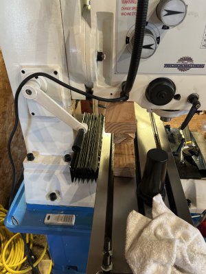
Info needed for installing/setting up pm940m

Nice but will it work on this size machine over cast iron or steel? Or it’s only for aluminum? I thought flycutters where used for facing
Fly cutters are for shallow surfacing and finish, face mills/large shell will face a surface and remove a lot of material at once. I have a 3" diameter face mill that I have used for cast iron, steel and aluminum in aluminum i can take a 0.300" deep pass, in cast iron and steel I have taken as much as 0.100" deep pass. Keep in mind that my face mill uses 6 carbide inserts where as a shell mill will not; but they do make face mill heads for those shell mill adapters.
 
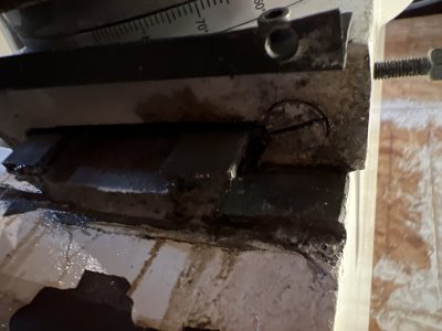
Definitely clean the ways. The first photo you showed of the crap on the top of the way is just junk and this surface is not important to operation, but should be cleaned off to keep the crud out of the ways. This surface in that photo does not make contact in the ways anyway. You can see the gap at the top of the saddle, it will be a couple of mm between the saddle and the surface that you showed as being so dirty. As far as oil is concern on this z-axis way, just put a puddle at the way corner at the top of the saddle, both sides, and it will drip down into the ways. Likewise at down z-axis gib. You can thank gravity. It will hang around a long time as you do not crank it up and down very often. The clamps on the pair Z-axis gib are poorly made in that they have small bearing surfaces against the gib. In my 940M these had bent the gib before I ever got it. If you get a big clamp and clamp the Head to the column at the ways without fear of it falling... so you can pull the gib out and take a look at it. I did this and found big dig marks in the back of the gib from these clamping screws. If the gib is too small or chewed off on the small end then the holding screw may be striking it on the side causing it to bind. If you do not have the gib locked down it will slide around and get looses when you are cranking one way and get extremely tight to appear to be binding when you are cranking it the other way. If you find that the cranking is tighter at one end of the column than the other then there is the possibility that the column ways are not cut parallel but flare out. Also, my geared head is too heavy for the ways. As the head tilts it tends to bend the column ways together when the top of the saddle is in the mid way up position. Yours may not be so heavy. Anyway, if I adjust the gib when the head is in the mid point of the z- column position I may make it too tight for the end positions. This is because of the gab between the column ways in the center as opposed to no gap at the ends. This gap is where the ball screw mount feeds through to the lead screw.

I try not do not use the screw clamps at all, but I have a CNC and the stepper motor holds the position when the power is on. When I power down I stick a wooden block under the head to keep it from falling.

If you want you could drill a hole in the side of the saddle for the Y-axis and install an oil port. If you hit the way interface with the drill bit you you will have to clean it up and smooth it out. So make sure the saddle is in a position that you can later expose by moving it over. Better still just wet down the exposed area under the bellows and move the y-axis back and forth a few times to spread it out. It is pretty exposed at the front when you move the y-axis toward the column anyway. Just oil it there. It will not hurt anything if there is too much way oil. Just a little messy and that is what milling is all about anyway. My mill has auto oilers built in and if I let it run as it was set at the factory the entire mill is dripping all of the time. It seems the oil reservoir is always always going dry!

I use Naphtha to clean my surfaces and ways. It does not take the paint off, but works well for the grease and dirty oil and even though it is what is called lighter fluid (smokers) is far less flammable that acetone. An acetone spill can mess up your painted surfaces that you want to keep.

Dave L.
Dave, I did not have much success adjusting my gib while the heads weight was on it, I had to set it on the table and make the adjustments and that worked very well.
 
  • Like
Reactions: B2
Dave, I did not have much success adjusting my gib while the heads weight was on it, I had to set it on the table and make the adjustments and that worked very well.
I understand. I agree that the weight on the head is a problem. I did not clamp the head to the column to adjust the gib, but I found that if I loosen the screws just a bit and go up and down the gib will slide one one way of the other. At one point the gib is a bit looser and so the screw can be moved. So one way for tightening it and the other way for loosening it. The + - direction depends upon the direction of the gib taper direction.
 
So I need to fix the head with 2x4 for support and check the gibs for damage bends from the locks.

For the pm940m what face mill/ shell mill do you guys suggest for cast iron steel. I don’t plan on being aggressive as I am relaxed on the time this is more for fun and make stuff up.

Also what motor driver are you using for the z axis. I might keep x/y manual but the z is definitely going electric.


You guys amazing, thanks a lot for the help
 
I adjusted my Z axis by watching the movement of he head when I tightened the gib locks. I kept tightening the gib until I saw little to no movement when hitting the gib locks, then fine tuned it by moving the head up and down making sure that the gib was not causing too much drag on the raise.

Blondihacks did a vid on installing a power Z motor on her little mill. Got it a s a kit from someone. Pirest Tools

PM may have the Z motor as a kit also.

OR....you could buy a power feed with a high torque motor/gearbox, make the adapter place and mount it yourself.... Here is how I did my "Y" axix power feed. Y axis mod just have to look at how to mount it and what you have to do to adapt a generic power feed.

***99% of what I work on is steel****

For face milling, I use a 2.5" indexable carbide face mill that would bolt up to the 2 ear arbor that came with the mill, and I also use a couple of smallish fly cutters. I need to get a larger one or build one for at least 6".

End mills, 1/2" is about the max I run. I could probably go larger, but 3/8 to 1/2 get the job done for bulk material removal. Feeds and Speeds is the key to it all.

Little Machihne Shop have a nice online calculator that I now have on my phone home page (web link) that is a pretty quick tool for figuring out your feed and speed setting based on the tool and the material.

i was checking around and the kit was like a few hundred $

then i searched here for 940 cnc conversion and foudn this thread:


It looks like the motor for direct drive needs to be around ~1600 in-oz. then looked at prices found motor and driver for around ~120$ and i am thinking to reuse a Arduino or esp32 and make it manually driver via buttons/potentiometer and double it later as CNC if i ever go that route. i already have a 350WAT power supply that i can use for it.


I know is a lot going on now for me but just trying to put stuff in perspective to where i might/need to go moving forward.
Being new did not account for the laborious task of moving the head by hand cranking a lot :p

Tim
 
I lowered the head on some wood pieces the lower screw for the z axis and unscrewed the bolt of the gib underneath a bit and the upper one too and the head will not move. How do I move the gib out to make it lose. On the downfeed is way easier then going upward.

Again sorry for my ignorance.

Tim
 

Attachments

  • image.jpg
    image.jpg
    276 KB · Views: 43
  • image.jpg
    image.jpg
    341.9 KB · Views: 41
  • image.jpg
    image.jpg
    161.4 KB · Views: 39
Last edited:
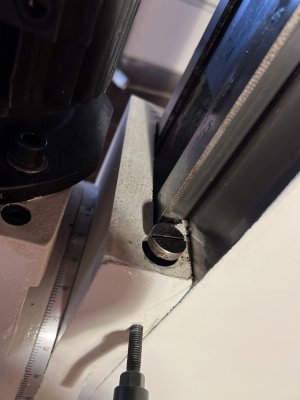
I mean I unscrewed the upper one a bit and the lower one too and the head does not rock. Then I tried to screw the lower one but it will not go in by much. I guess that is the bolt that pushes the gib upward and out I guess
 
I mean I unscrewed the upper one a bit and the lower one too and the head does not rock. Then I tried to screw the lower one but it will not go in by much. I guess that is the bolt that pushes the gib upward and out I guess

The idea is that you tighten both screws down to keep the gib from moving. If the gib is not trapped then when you move the z-axis up and down the gib can slide around and be loose in one direction of motion and over tight in the other direction of motion.

If you want to loosen the gib, back the screw at the big gib end away from the gib and then tighten the screw at the small end to push the gib out a bit. Use small steps.

To tighten the gib you do the opposite.

If the small end of the gib is too small it may slip past the screw head and then the screw will just wedge in gib end between the screw head and the way. This is not good as it just works like a clamp and not an adjustment. (This is the way, my mill arrived new!) The small end can get worn off if you tighten it too much without having the big end screw loose! There is only a smallish corner of the gib that catches on either screw head so be gentle and don't mess them up.

On my mill the threaded holes for the screws are loose and this allows the screw head to wobble too much. So I made a washer the size of the screw head, but that has a finger like shape that sticks out a bit to catch the worn small gib end.
 
Back
Top