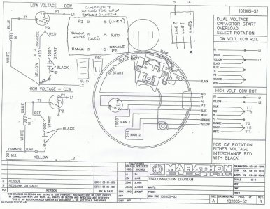
Is there a single phase 220V rotary reversing switch?

cobbonthecorn

Registered
Registered
Joined
Dec 31, 2014
Messages
8
I have just taken delivery of a Logan lathe with a single phase motor wired for 110V and it is equipped with a 3 pole rotary reversing switch. I know how to wire the motor for single phase 220V operation but to use a rotary switch I need one more switched leg to handle the additional hot line coming in. I have search high and low and not found a solution. Do I need to add a 220V switch for power and leave the drum switch for forward and reverse? Thanks in advance!
 
if i'm reading you correctly,yes you can use your existing drum.
a 3 pole drum could be configured to switch 2 hot leads for directional control.

pictures of you motor and associated wiring would be of great help on my end.
otherwise i can only give general answers.
 
The rotary drum switch is a Furnas R2532. It is currently wired and operating in the Low Voltage mode with reversing. I am wanting to operate in High Voltage mode with reversing. Tks on suggestions.
Capture.JPG

Capture.JPG
 
can you post a picture of the switch?
i'd like to see if i can reconfigure the switch to suit the need.
i didn't get much from the google search


the best i can suggest for wiring right now for 220v is like this for the current switch layout-
(Terminal 1 top left) P1
(Terminal 2 top right) L1
(Terminal 3 middle left) Yellow/L2
(Terminal 4 middle right) Red
(Terminal 5 bottom left) Black
(Terminal 6 bottom left) Orange/White

the difference between the motor wiring for high and low voltage, the low voltage windings are connected are in parallel,
for high voltage operation, the run windings and start windings are connected in series .

if for any reason this doesn't work, give a holler and we'll bird dog the problem down!
mike:))
 
Last edited:
Just some items related to moving Hot's around... In my past, we would alway's use a relay's / or contactors with some manner of low voltage control to move hot's or swap hots. There are also numerous industrial OTS items to do this too. There was never anything but low voltage on any user panel or switch. To this day I can still remember when the Boss came over and told me why we never put hot AC to places where users or tech's may wander into. You could setup something really quick w/ a 5v or 12 relay and contactors as well. Remember if the motor current is high and you flow that around and thru Drum switches you need to make sure both the wire and switch can handle the amperage. Now all this industrial gear is much different than my electronics and digital work so maybe it is more common on this stuff since you really do need to manage motor V/I (voltage and current) along w/ switching and reversing all over the place.
Just some general comments is all. I'm sure many many do this and it's fine 99.99 % of the time. Keep us posted.
CG
 
It looks like you do need both a 2-pole, single throw [DPST], 250V switch to disconnect power to L1 & L2 & the reversing switch to change motor direction; otherwise you'll need a 4PDT, 3 position, center-open switch. The reason it worked with 120 VAC was that you only switched 3 wires because the neutral didn't need to be switched so you only needed 3 contacts. Here's a rough sketch in case you need to see how to connect the reversing switch. Hope this helps.

View attachment 240V Rev. Mtr.pdf
 
That is the impression I have each time I look at the circuit. I found a nice looking switch at Grainger (6A611) from Advance Controls (101470G) that should work. 600 V, 20A, 2 pole, single phase.
 
That is the impression I have each time I look at the circuit. I found a nice looking switch at Grainger (6A611) from Advance Controls (101470G) that should work. 600 V, 20A, 2 pole, single phase.
The start windings should already be connected to the drum switch, plus the power wires to the main windings. The main windings are either connected in series or parallel for high or low voltage in the motor, not the switch. Have a look at one of these diagrams
http://electricmotorwarehouse.com/IMAGES/RS1_diagram.jpg
http://electricmotorwarehouse.com/drum_switch.htm
Look at the split phase diagram
 
Back
Top