Just brought home a South Bend 9A...

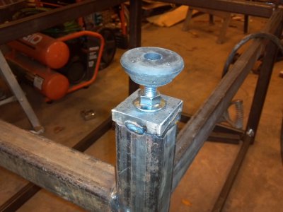
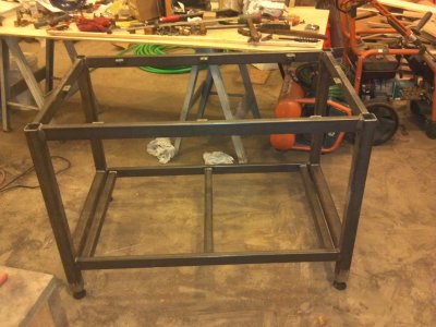
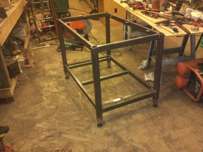
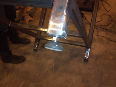
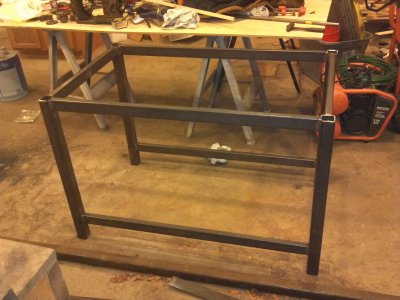
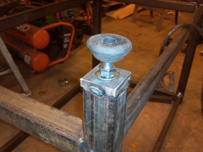
Worked a little more on the workbench yesterday. Got a couple cross braces welded on and got the pads made for the adjustable feet. Got one foot pad tacked onto a leg. To make the foot pads, I cut 2X2X1/2" pieces from a piece of 1/2" X 2" bar stock, ground them to clean up the edges, then chucked them in my 4-jaw to drill and start the 1/2 - 13 tap. Then I welded a 1/2 - 13 nut to one side to give additional thread and strength to hold the foot, then tacked it to the end of the leg. I'll finish the welds on all four sides, then grind them smooth, just for looks. I will weld 6 tabs to the top members, which will be used to attach a top made of 1-1/2X2 lumber bolted together and finished with boiled linseed oil. That will probably get a sheet of 10 ga steel on top of it, to make it more durable and easier to clean. The workbench will get Rustoleum primer and Rustoleum black paint. Later, I'll build a machinist tool chest full of drawers to fit under the worktop.

Fun.
2013-12-10 18.13.30.jpg2013-12-31 13.09.01.jpg

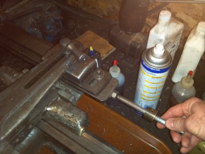
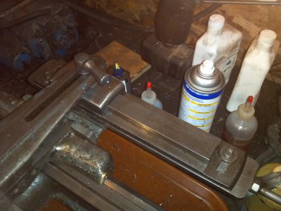
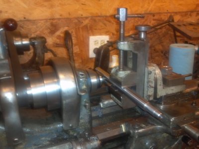
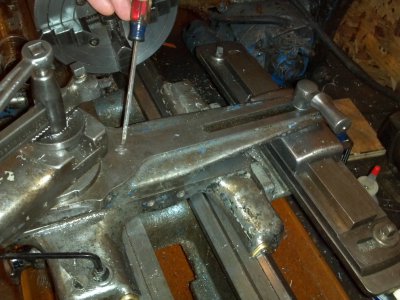
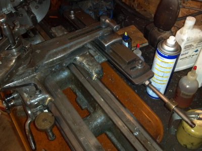
I also took some pictures of the taper attachment, while I was answering some questions on another thread. Thought I'd go ahead and post them here. I have what is called in the South Bend catalogs as a "Plain Taper Attachment", which means you have to remove a screw in the cross slide that retains the cross feed nut in order to use the taper attachment. When the taper attachment is used, a bed clamp (which my unit is still lacking) is clamped to the bed and the screw mentioned is removed, and the handle you see on the taper attachment is locked down, thus allowing the cross slide to move with the taper attachment as it slides along its length, which is set at the desired angle. When the taper attachment is not in use, the bed clamp is loosened, as is the handle on top, and the screw is replaced to secure the feed nut. The whole taper attachment then moves parallel to the bed with the carriage, longitudinally, and the cross slide is again operated by the handwheel. Because of that, many people remove the bed clamp to avoid needless wear from it sliding along the bedway. Somewhere along the way in the life of my lathe, the bed clamp got separated from the lathe and was lost. Apparently this isn't an uncommon problem, as I have seen a number of taper attachments that are missing the bed clamp bracket. I have located a bed clamp, but must wait a bit to buy it (Christmas must get paid for first, you know).
2013-12-31 13.03.28.jpg2013-12-31 13.03.41.jpg2013-12-31 13.04.31.jpg2013-12-31 13.04.41.jpg

Lathe is a little dirty, since I had just finished drilling and tapping the workbench feet. Can't wait to be able to take the lathe down and clean and paint everything. Got to get my DR operational first.

2013-12-10 18.13.30.jpg 2013-12-31 13.09.01.jpg 2013-12-31 13.03.28.jpg 2013-12-31 13.03.41.jpg 2013-12-31 13.04.31.jpg 2013-12-31 13.04.41.jpg
 
Tony, I thought you were not supposed to use the tail stock when turning for alignment, it should only check the head vs. the carriage. Tim

I haven't read that particular book, but others, including the South Bend book, say you can align the lathe by turning a test piece and measuring near the chuck and near the tailstock center. You're actually supposed to turn it between two centers, but I just dialed-in my 4-jaw with a tool in the holder and did it that way. The long and short is that if the lathe is turning both ends the same diameter, it's good. My test piece wasn't as long as recommended, and I didn't worry about polishing it or getting a perfect finish, but it's good enough for what I'm doing right now.

Maybe somebody who has a little more experience could chime in here and give us a little coaching.

Hi Tony,

Sorry to tell you this, but adjusting the tailstock to turn a test piece between centres to the same diameter at each end, does nothing to adjust the lathe to turn truly parallel. You can adjust the tailstock to give you the same diameter at each end of a long test piece, but a piece held in the chuck will be machined out of parallel if the bed has an induced twist in it. And you cannot "pull" the free end of a workpiece into the right place with a tailstock centre.

The correct method is to bolt the headstock end of the bed solid to the bench, then tighten the bed hold-down bolts at the tailstock end firm onto appropriate pieces of shim material, to reduce the chance of inducing a stress (twist) into the bed casting while taking the first test cut.

A piece of easy machining material, I use aluminium, approx 1"+ dia and 6" long, is held in the 4 jaw chuck, without any support at the outer end. The centre section is turned a little smaller (undercut) than the ends, to leave a "collar" at each end. A light cut is then taken over the raised "collar" sections at each end, without changing the cross slide setting.

If the OUTER collar is LARGER than the Left Hand collar, it means the tool is moving away from the workpiece as the carriage moves along the bed from left to right. That is, the bed has a slight twist in it. Therefore a shim should be placed under the FRONT of the tailstock foot of the bed or the front leg if the lathe is on a stand. The hold-down bolts are tightened firm on the shims, and another very light cut is taken.

If the OUTER collar is SMALLER than the LH collar, the shim goes under the REAR of the tailstock end foot. The hold-down bolts are re-tightened after each test cut, and remain tight when the lathe is finally turning PARALLEL, which may require quite a few test cuts. ONLY NOW do you adjust (align) the tailstock to turn a shaft parallel between centres. I think South Bend's "How To Run A Lathe " and other books describe how to set up a lathe. It makes no difference if the lathe weighs 200lbs or 2 tons, or even if the lathe is level or not (Lathes in a ship's workshop are level only every now and then!). It is the STRAIGHTNESS of the bed ways when the machine is bolted down that matters.

Regards, RossG
radial1951
_____________
 
Last edited:
Actually, the procedure of turning a test piece held between centers to give the same diameter on both ends is for zeroing out the tailstock backset. It assumes that the bed is already straight and level.

Unless you are actually aboard a DD or an AD, the quicker method for leveling and removing any twist from the bed is with a precision level.

Robert D.

CWO4 USN Ret'd.
 
Worked a bit more on the workbench for the lathe today. Had my son-in-law here to help and things went fairly quickly. Time to come in now and do my granddaughter duty. Some pics for your enjoyment.

2013-12-31_13-09-02_780.jpg2014-01-03 13.49.52.jpg2014-01-03 13.50.05.jpg2014-01-03 13.50.18.jpg

Too bad I decided to grind off the feet to blend them with the legs. Made it so you can't see my beautifully flawless welds:biggrin:.

The bottom will get a 1/2" ply floor and the top will be 2-1/2" pine, made up of 1-1/2" X 2-1/2" boards (cut from 2X4s) bolted together with 5/16 threaded rod to make a 30X48" top. The top will get several coats of boiled linseed oil and a piece of 10 ga steel overlaying it. Got most of the woodwork done today as well. I just lack drilling the wood for the threaded rod, bolting it all together, and applying the finish.

2013-12-31_13-09-02_780.jpg 2014-01-03 13.49.52.jpg 2014-01-03 13.50.05.jpg 2014-01-03 13.50.18.jpg
 
This week I repaired two vehicles and a washing machine, but today I finally got back to working on my lathe rebuild.

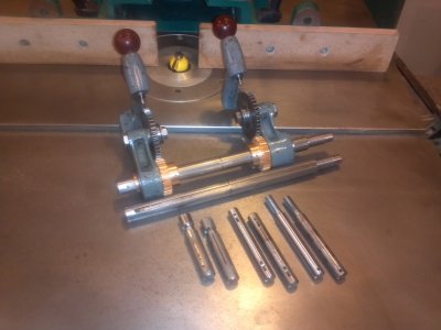
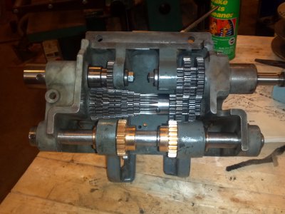
Finished cutting the keyways on the shafts for the DR11 apron and gear box, which I made on the South Bend 9A.

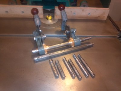
Got good use out of the Palmgren Milling attachment I bought for the job of cutting the keyways. Learned some things on the way. Firstly, make sure everything is locked down tight before you start milling! On my first try the milling attachment moved, breaking my 3/16 end mill bit and leaving a small tell-tale mark on the shaft. Not a big problem, just a learning experience. Shaft is fine. I'm pleased with the way they have turned out. In fact, they have turned out so well, I have decided to replace three more shafts in the gear box that I had originally decided to leave as-is.

2014-01-18 12.12.31.jpg2014-01-18_09-36-17_892.jpg

I had to cut the 3/16 keyway in the 3/4" shaft for the tumbler gears using a 3/16" end mill. Since the shaft was longer than the range of my cross slide, I had to cut the keyway from each end, meeting in the middle. There is a ring clip that divides the two ways for the tumbler gears in the middle, so I milled the slot from each end to the clip groove. Had to get it just right, because both tumbler gears must be mounted from the same end of the shaft and the right one must be able to slide past where the two keyways meet in the middle. Came out perfect.

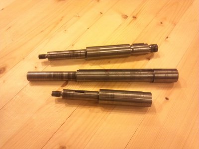
In the picture of the shafts, the originals are on the right and the new shafts on the left. I learned a lot of different operations in the process of making them. One of the shafts I'll be making next week has two diameters in the middle (3/4" and 1/2") and different size threads on both ends. Should be a fun and interesting challenge for me.

2014-01-18 12.12.31.jpg 2014-01-18_09-36-17_892.jpg
 
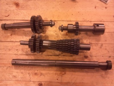
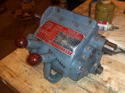
Well, I have finished all the replacement shafts for the gearbox of the Delta Rockwell 11" lathe. Sadly, just after threading the end of the last shaft, the South Bend's gearbox jammed. I haven't figured out what happened yet, because I haven't been able to take it apart yet. I still needed it to finish milling the keyways in the shafts. I was able to do that by disengaging both tumblers, so that the spindle would turn, but, of course, I have no auto feed. I was able to successfully cut all the keyways, using the milling attachment and hand feeding.

Now, if anybody has any ideas about what to look for in the gearbox of the SB9A, I'd appreciate the help. Now that I have the DR gearbox back together, I should be able to take time to look into the SB's gearbox.

2014-01-18_12-12-32_780 (1).jpg2014-01-18_13-47-00_831.jpg2014-02-08_16-33-16_765.jpg2014-02-11 14.49.18.jpg2014-02-11 14.49.30.jpg

Pictured are all the shafts I made on the SB9A for my DR11, along with the originals.

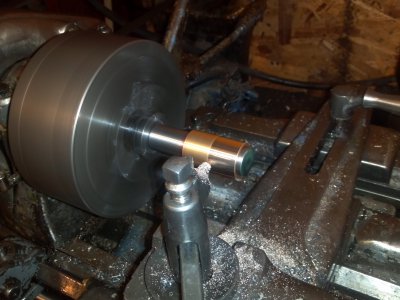
I also replaced all the bushings in the DR gearbox. I found the ODs of the bushings to be between .007 and .010 too large for the holes they were supposed to fit in. I used the SB9A to make mandrels, on which I turned down all the bushings to about .002 over, for a press fit. I also used the SB to make my own bushing driver set to install the bushings.

2014-02-06_14-30-43_730.jpg

So, finished with that project. Now I need to get the DR working, so I can take down the SB9A and overhaul it.:))

2014-01-18_12-12-32_780 (1).jpg 2014-01-18_13-47-00_831.jpg 2014-02-08_16-33-16_765.jpg 2014-02-11 14.49.18.jpg 2014-02-11 14.49.30.jpg 2014-02-06_14-30-43_730.jpg
 
Back
Top