- Joined
- Dec 25, 2011
- Messages
- 10,511
The nylon patch set screw is about the only fix for the spindle cone pulley problem other than replacement.
The belts are 3/8". Strangely, no one with apparently original belts has ever reported the rest of the belt industry part numbers for the 101.07301. For the 618 with bench mounted motor, we have motor belt as 3L210 and spindle belt as 3L350. But almost all 618's still in existence have a different countershaft bracket. The safest thing to do would be to buy a pair of them from Clausing.
They do make link belts for 3/8" pulleys but anyone who tries to restart that argument will be treated harshly. 'way more than enough space has already been wasted on it.
As far as measuring for the required belts, the usual method is to mount the countershaft bracket per the drawing. Position the belt tensioner at the middle of its actual adjustment range, and wrap a 3/8" wide preferably cloth tape measure around either of the two middle pulley grooves. Round off to the nearest inch, and buy one that length. Note that the industry belt part number is standardized as a 3 (for 3/8" wide, the letter "L", and a 3-digit number with is the belt length in tenths of an inch. So the 3L350 previously mentioned is 35.0"long. The belts used on all of the Atlas machines except for two of the four on the 12" cabinet models are known as fractional horse power belts, or FHP.
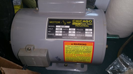
 At least it is an unused motor, that spins smoothly when power applied.