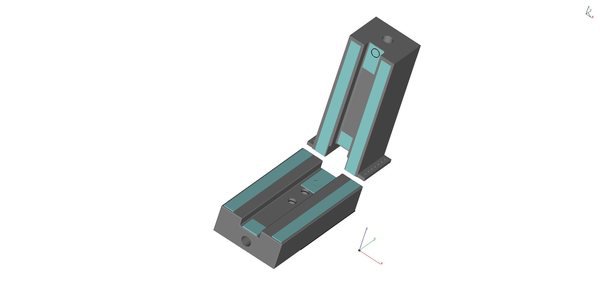
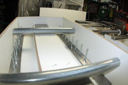
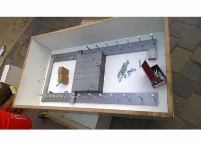
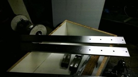
A key point to the design is using 2 steel bars ground to .001" on all sides and 1/2"x3"x36". Each bar weighs a lot. I am aligning the bars and bolting them to each other with the cross members embedded in the epoxy for strength. That way I can pre drill the holes and fix them precisely by bolting them through the mold using coupling nuts which will serve as anchors for them. They will form a coplanar mounting platform for both the linear rails and the mill column.
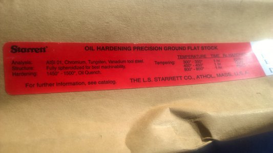
I am aligning the two 3x36x1/2 precision ground bars parallel using a 12" granite surface plate. Then I will align them on the same plane by cross bolting 1 x 1 precision ground bars to fix them in place aligned.. Once cast into the epoxy base this assembly forms the basis for both the y axis and the vertical column for the z axis which will also use 2 ground steel bars aligned the same manner as the base.
Finally, I am going to cast in place a 15x15 ground plate "frame" on the bottom of the z axis. After reading about using grouting for alignment, I will use this method and have jack screws to do the final adjustments and then grout.
All the ground bars are being drilled and will be through bolted in the mold using coupling nuts to hold them in place.when I cast the epoxy granite. This should provide a precision ground and aligned surface to do final indicating of the rails.
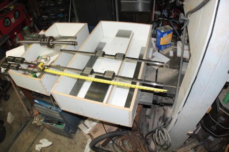
I managed to drill the steel bars for the 30mm linear rails. I was worried about the prospect of drilling 18 holes through tool steel all aligned but it worked. I had to do 3 different setups on my rf45 clone for each rod. I bolted one of the linear rails direct to the table and indicated it straight and then used that as a straight edge for steel bars. Really made me wish I had a bigger mill! At the end, every single hole witnesses the linear rail holes.
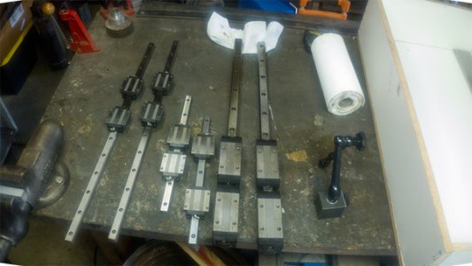
As far as the size of the linear rails, they were selected on the basis of the largest I could afford and fit in the design. I got all of them on
Ebayand they were new stock. I averaged 200 per axis for rails and guide blocks.
The Y axis has the most forces on it because it has the x on top so I went with the extended version THK SHS30. They are going to be 15" for maximum rigidity. I can get a decent amount of deflection cutting steel on the RF45 and this is one area I wanted to really improve.
The X and Z have less force and going with the 20mm THK SHS to provide more range of motion.
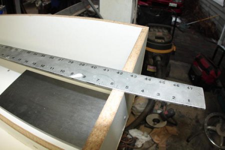
To get an idea of the footprint of the machine, The base is 22"x42" x 9" and will weigh over 800 lbs by itself before adding linear rails, ballscrews and servos.
I expect the whole machine to come in around 2700-3300 lbs(1225-1360 kg)
Envelope for each axis is:
X: 22-24"/560-600mm
Y: 15"/380mm
Z: 18"/460mm
Trying to find a 7-8 hp spindle.
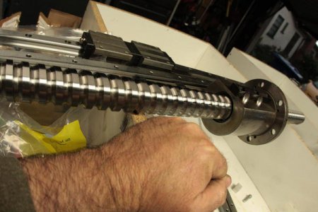
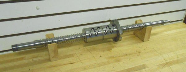
I got a 40mm THK ground screw and another ground ballscew for Harding that is a double nut. Both are larger than my original design so everything got supersized.
