- Joined
- Feb 5, 2015
- Messages
- 662
Part One
(These are a collection of quick-fix anecdotes written several years ago and mainly intended for entertainment. Because readers vary in levels of experience and knowledge, I'm aiming at the novice. More experienced readers will have devised their own means for performing the operations that I've included. This is a post that I've been working on for a while and it is long-winded. I've tried to break it down into logical sections to avoid boredom.)
Introduction
The tailstock is a necessary but unglamorous feature of an engine lathe. We use it for drilling, reaming, tapping, centering and sometimes as a light arbor press but otherwise give little respect to the cast-iron appendage parked at the end of the ways. A bed-turret ? Now we're talking - THAT is something a home machinist can get excited about, but I get a lot of use from the tailstock.
The best machinists that I've worked for (or with) were characterized by invention in addition to their obvious knowledge and skill. The ability to configure an unconventional setup for a special task … to create a "fix" that reduces time, improves finish or precision … design a special tool for a specific job.
These often make the difference between a successful job shop run by an inventive owner or manager and one that goes belly-up after a year. (I worked in both environments, as a young man. Preferred the shop with a constant pay check, LOL, although frankly I didn't learn as much from the experience.)
After retirement and relocation from a major urban area, I established a home business. My work was engineering consultation, most often proposal work: specification analysis, creating a system architecture to provide the specified performance, estimation of development and production costs and sometimes detailed designs - all electronically transmitted to customers located in the San Francisco Bay Area.
Sounds nice, right ? Clean hands, nothing much to buy except copier paper, LOL. BUT sometimes a customer required measured performance data - prototypical "proof" of the key design aspects on which the system performance might depend. This involved making, assembling and testing microwave circuits comprised of fairly small parts, usually machined from non-ferrous materials (One bedroom of my house has been configured as an electronic test lab). Microwave "circuits" don't normally look like how most of us envision electronics.
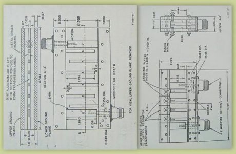
Here are two examples of microwave circuits, photographed from a nineteen-sixties textbook. Note that the technology has come a LONG way beyond this and not just by decades ! One aspect of these circuits hasn't changed: the precision required. The two bandpass filters shown below were produced to locational tolerances of +/- .002 and thickness/cavity dimensions of +/- .0005 - fairly typical for state-of-the-art at that time.
These examples are representative of vertical mill operations but lathe operations were also required to produce microwave circuits to these tolerances. These examples were produced long before digital readouts and on manual machinery by skilled operators using techniques that were once common knowledge. (Sorry about the quality of the drawings - my digital camera is the copying machine.)
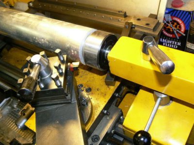
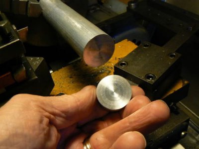
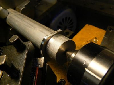
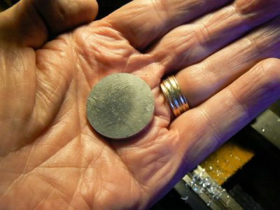
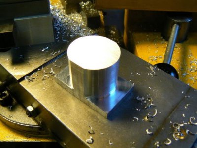
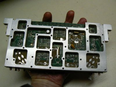
The following photo depicts the LARGEST single part that I've made in years:
Before relocating, my machine work was subcontracted to quick-reaction (= small) local shops. In my present semi-rural location, those resources weren't available so I had to tool up and resurrect old skills so that I could make the critical parts myself, LOL. The equipment in my small shop reflects my needs (small lathes, small mills, small welders, small inspection equipment, small everything)
But occasionally parts outside the normal capability or work envelope that the machine designers intended are required. I had some machinery and welding equipment before moving but required additional capability (mainly the two mills + tooling). Given my limited floor space - shared with a wood shop - unconventional solutions to some problems were suggested.
"Centerless" Operations
My first "real" machine tool was a used 6 x 18 Atlas lathe purchased around 1968, configured for rebuilding motors and generators. The keyless tailstock "commutator chuck" opened to 3/4 (or maybe an inch) diameter and had bronze jaws that resembled rounded vee-blocks. Journals of motor and generator shafts (or similar rotating workpieces) could be secured in the tailstock, free to rotate. The chuck functioned like a small steady rest but was much quicker to install, required minimal adjustment and produced good results - which gave me the following idea.
For working small diameter centerless ground shafting and the like, a convenient substitute for the commutator chuck (or for a center) is to turn a brass or bronze bushing that fits the tailstock drill chuck then bore/ream a running fit to the shaft to be centered/supported. (It's a good idea to cross-drill the bushing for an oil hole so that the work can be lubricated while turning if the operation involves substantial pressures or lengthy duration. This can also be a convenient means of ejecting short parts, with a jet of air.)
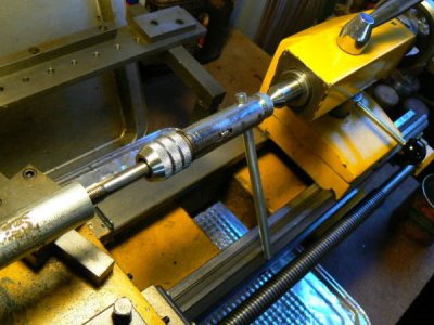
Eventually, I made rotating tailstock chuck using an old Jacobs 18N chuck, a hardened ball and a long oilite bushing. At first glance it looks like a conventional drill chuck. Looking closely, one can observe that the shank of the chuck is actually in two pieces. One of the three set screws that ride loosely in a groove can be seen. The purpose is to hold the two pieces together.
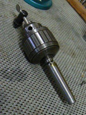
Note that this type of end support isn't normally used for long turning operations, where substantial amounts of taper might result from a slightly misaligned drill chuck. However the practice can be useful for short lengths, when requirements are not critical. In the example that follows, a length of ground shafting is supported so it is possible to fine-tune the tailstock alignment by sweeping the work with a DTI if greater precision is required. Those learning this craft should not be averse to changing tailstock alignment, which may be necessary for many operations - tapering for example - after which, re-centering will be required.
Shown below is a length of 7/16 diameter ground shafting supported in an oilite bushing that I was fortunate to have on hand - didn't have to make a bushing. The end of the shaft was de-burred and lightly sanded before insertion into the bushing. These are inexpensive and convenient to have around the shop - add a couple of them to each order from your normal tooling distributor and a respectable inventory will soon accumulate. The purpose of this particular operation, BTW, was to produce two "O" ring grooves near the end of the shaft. Drill bushings can be even more useful since they don't wear rapidly as do bronze bushings.
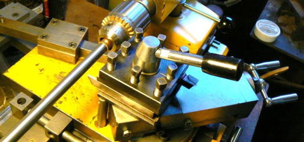
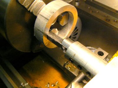
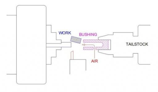
Incidentally, this can be a fairly good way to part off and collect short workpieces, instead of digging through the chip pan trying to find them - for occasional work. The bushing in the tailstock fully supports the parted off work so the little "nib" remaining on the work is almost non-existent. The tailstock is run up to the work so that the workpiece is partly enclosed in the bushing (it's unnecessary to clamp the tailstock to the ways - moving the tailstock by hand allows rapid engagement and withdrawal). A little slot or hole in the bushing allows ejecting the cutoff part, if required with a short blast of air.
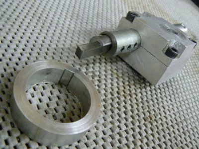
It's helpful to grind the parting tool with a slight angle. Looking downward on the tool from above, the right edge (closest to tailstock) of the tool should part off the workpiece before the parting tool removes the nib from the stock held in the headstock chuck or collet. I tried to photograph this operation but the details were fuzzy; here's a sketch that might convey the shape of the parting tool better. As noted above, the stock needs to be de-burred before insertion into the support bushing but that should be an automatic reaction during parting operations.
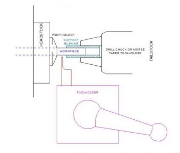
Incidentally, if drill bushings are used in an application like the one shown above, cross-drilling holes for air ejection isn't practical. There are other possibilities for the HSM, the most common is the use of cheap diamond tooling in a die grinder (or Dremel tool). Both 1/8 and 1/4 shank diamond tools are available from most importers at throwaway prices (e.g. $6/dozen).
Measuring From The Tailstock
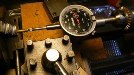
A simple measurement tool originally constructed for the vertical mill has also been useful in the lathe tailstock. Here's a description, a photo of the tool and the reason for making it. The tool consists of a 1/2 inch arbor (turned eccentric from 3/4 stock), bored to accept the stem of a travel indicator and slotted for clamping with a small socket head cap screw. (The shank must be clearance drilled about 1-1/4 inches deep so that the indicator spindle can travel up into the arbor.)
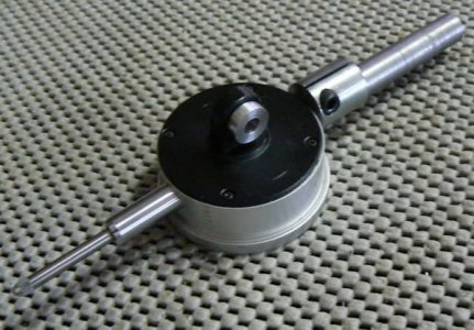
The original intent was to be able to adjust a workpiece, held in the milling vise - to a shallow angle with better precision than a spirit-level protractor head (when sine bar, gage blocks or angle plates weren't available or when time was limited). The process commences with the workpiece lightly clamped and adjusted to the approximate angle with the spirit level, then fine-tuned by gentle tapping with a soft hammer, monitoring progress with the indicator (it is helpful for the lowest end of the part to be supported in the vise with a small spacer or the end of a parallel, providing a "pivot point"):
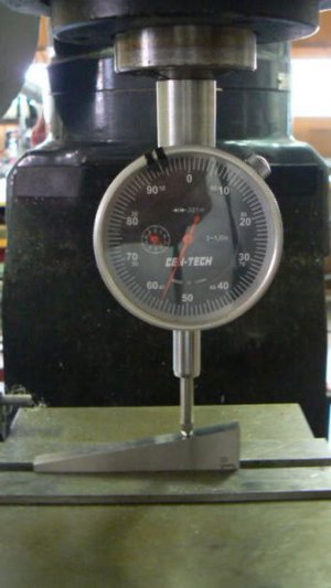
The travel indicator is first zeroed at one end of the workpiece, then the "X" axis is offset by a known distance (determined by handwheel graduations or DRO) while holding the indicator spindle retracted by hand (so that it doesn't deflect from friction). Gently lowering the spindle of the indicator until it contacts the workpiece after the table has been offset, the indicator displacement is noted. (Although a "ball end" is shown in the photo, a flat end is OK for this application.)
The angle is determined by taking the arctangent (tan-1) of the two known distances. In the example above, the table has been displaced exactly 2.000 inches, according to the X axis dial count while the travel indicator shows a vertical displacement of .356 so the angle = tan-1 (.356/2.000) = 10.093 degrees.
[For the photographic example, an imported 10 degree angle plate was supported by a pair of imported parallels.
I didn't expect too much from the angle plate but thought that it should be more accurate than the measured 5.5 minutes (.093 degrees) of error. Removing the angle plate, I swept the parallels with the travel indicator and found an error of .0015 (the vise contributes to that error, too). If I subtract the error from the .356 previously measured, I get an angle of 10.05 degrees and an error of 3 minutes which is slightly better. After initially writing this, I looked at the catalog specs of the Enco angle plates and the measured angle is likely typical of the product.]
The example indicates the utility of a simple, inexpensive tool to determine angular accuracy (shallow angles) when one has neither sine bar nor gage blocks. The example also illustrates that imported tools, while seemingly good value for the money, need to be examined carefully when used in a setup that requires precision. (One of these days, I'll repeat the test using a sine bar and gage blocks, as an exercise.)
(Oh yeah … when the correct tangent reading is obtained, the vise is tightly clamped, checking one more time to be sure that the angle is correct.)
I've found other uses for the indicator/arbor … like setting stops on a drill press or precisely adjusting quill travel stops on a milling head. The indicating tool allows fairly accurate machine settings while installation/removal is quick and convenient. One of the most common uses is checking the level of work installed in the mill vise - slip the tool into a 1/2 collet and quickly run it front-to-back across the workpiece to check that it hasn't lifted enough in the vise to be problematic. (Any DTI can do this; it happens that the length is convenient for the purpose.)
Another application for this tool - similar to the last one - is setting a parting tool parallel with cross-slide travel. The measurement tool is installed into the collet/chuck in the headstock, and the cross-slide moved while the runout of the parting tool is observed with the indicator which rests along the top edge of the blade, adjusting the blade until there is no runout before clamping.
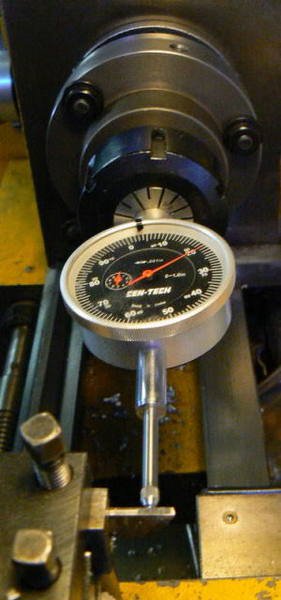
Sorry for the divergence - returning to topic, a convenient application for this device is in the lathe tailstock chuck. In above paragraphs discussing parting, I was reminded of how handy this measurement tool has been when parting off rods of various lengths in small quantities. The indicator is held in the tailstock and zeroed against the freshly parted face of the stock material (carriage is locked throughout all of the parting operations). Loosening the workholder (headstock chuck) slightly, the stock is extended until the indicator reading is the desired part length + the width of the parting tool. After tightening the 3-jaw chuck, the tailstock is retracted and the piece parted off to a precise length.
This is most useful when a number of parts of differing lengths are required and the tailstock is not required for supplementary operations such as drilling. If a number of parts of identical length are required, there are simpler means of performing the parting operation. In fact, extending that concept to its logical conclusion, a drill bushing secured in the chuck could provide both production stop and work support during parting.
Reviewing the sketch shown previously concerning the parting tool and the tailstock bushing supporting workpiece conveys the idea, I hope. (In addition to deburring the leading edge of the workpiece it's necessary to vacuum or blow out the bushing from time to time, freeing any small chips that may have inadvertently found their way inside.) Both operations can be performed simultaneously with a puff of shop air if a small hole is cross-drilled near the tailstock end of the bushing.
In short, an indicator tool like the one described, whose spindle is exactly in line with the 1/2 diameter shank, can be useful several times a day. Imagination is the only limit and I'm still finding applications for this simple device.
Tailstock As Drill Press
Securing, guiding and moving tools and workpieces has always required imagination combined with skill and experience. In cramped quarters, such as tiny workshops in small deepwater ships, sometimes only an engine lathe with a milling attachment can be accommodated so the drill press function is often performed by the lathe.
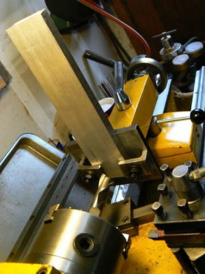
A friend was a machinist's mate on a U.S. Navy destroyer escort (during the Vietnam thing). I've enjoyed and learned from his anecdotal experiences of repair operations performed using a 10 inch South Bend, a milling attachment, welding equipment, hacksaw, chisels and files and his personal ingenuity. Some of the notes in this discussion resulted from conversations over a pint of beer or two.
Tapers
Short tapers can be easily cut using the compound-slide although there might be more unsupported tool overhang than we'd like. Long tapers are usually turned by offsetting the tailstock if the lathe has no taper attachment. Many newcomers to the craft don't care to disturb the alignment of their tailstock but only a few moments are required to re-align the ram by sweeping the Morse taper bore with a DTI held in the headstock (provided that the lathe ways are not overly worn and that the headstock is properly aligned).
Similarly, it's not difficult to offset the tailstock using a travel indicator to determine the proper offset (after first determining the length of the taper and solving for the tailstock offset). Use the appropriate trigonometric function of your pocket calculator to calculate the offset: tangent if the centerline length is known, sine if the tapered length is known. (If the travel indicator is left in place and not disturbed by the cutting operation, the tailstock can be returned to original position, after the taper has been turned, in less than a minute.)
Note that the "coincidence" of tailstock and spindle is a complex definition. Concentricity, axial/angular alignment of the two largely depends on where the tailstock is located, along the ways and how the machine is established on its foundation. This may not concern home machinists … because the tolerances we need to produce, the age of the machinery that we own and the lack of a production schedule allows us to take our time and produce acceptable fits with mating parts in the mechanisms that we design or modify. The alignment of headstock to tailstock to carriage has been discussed many times, most recently in this thread:
http://www.hobby-machinist.com/threads/two-collar-test-how-close-is-close-enough.31435/
In some setups, a hardened and ground steel ball is a better center than the standard 60 degree configuration provided that the cuts are not heavy. An expression frequently used when describing a tailstock offset to turn a taper is that the tailstock center "wallows out" the center-drilled hole, distorting the configuration. For shallow angles, this may not be critical but for larger angles a hardened ball can be a better idea.
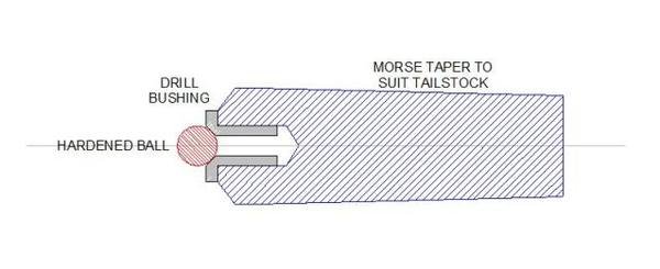
In the above arrangement, a tapered arbor has been bored for a standard drill bushing (the drill bushing clamping method isn't shown but will be discussed later). By changing the size of the inexpensive drill bushing, various sizes of hardened balls may be accommodated, depending on the size of the workpiece. This is a versatile tool because drill bushings can also be used to support long workpieces (as described in the "centerless" paragraph above) when it's not possible to use a tailstock center. Both drill bushings and hardened balls can be readily and inexpensively obtained from your normal tooling distributor.

Many ingenious ideas have been implemented for offset taper turning. The most common seems to be replacing the normal tailstock center with a boring head. With a small 60 degree straight-shank center installed in the boring head, adjustment of the taper offset with precision is not difficult. Except for the large diameter fine pitch threads, it's not particularly challenging to make an arbor for the boring head with the appropriate taper for the lathe tailstock, keeping a couple of points in mind.
The possibility of the entire assembly rotating in the tailstock must be considered and some means to prevent this should probably be devised because the load imposed by the cutting tool may encourage torsional movement at the tailstock. Rotation isn't as likely as another problem: flexing of the center, which isn't good for accurate work. If the center is offset from the ram - as it will be when held in a boring head - the center will not be located along the load axis and deflection is unavoidable. It may or may not be a problem, depending on the accuracy required, material, cutting load and the load imposed by the tailstock ram.
Boring heads are designed to support centrifugal displacement due to their mass, the negligible weight of the cutting tool and a modest cutting load - they aren't intended to replace the function of the tailstock center, especially when supporting heavy weights combined with heavy DOC and feeds. I prefer the previous arrangement (tailstock ball center and offsetting the tailstock) because it avoids all of these problems.
As mentioned previously, adjusting tailstock offset and restoring it on center is not a difficult or lengthy procedure using a DTI. If one keeps a test "dumb-bell" handy, it's literally a matter of a minute or less. A test dumb-bell is a workpiece that has been turned between centers to align the lathe or the tailstock. If the two ends are exactly the same diameter - as they should be - then moving the carriage with DTI attached, comparing the two diameters allows quick, accurate centering of the tailstock. (This was discussed extensively in the post that was referenced above.)
Thread Chasing
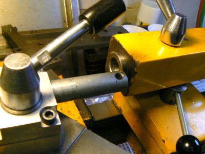
One of the most useful tailstock applications for small lathes is chasing threads (small diameters and/or long lengths) although this is a function more often performed by turret lathes and speed lathes. The shop-made tool shown below passes over the carriage with adequate length to work up to the headstock. Short pieces of steel rod, salvaged from under the bandsaw, are welded to both ends of a length of steel pipe.
One end is turned to suit the tailstock taper and the other end is turned concentric in the same set-up. Two opposed slots are milled through the pipe, just behind the die head location, to allow clearing chips. I performed a primitive stress relief in the kitchen oven after welding and before finish machining the tool. (Three cycles from room temperature to 400 degrees F, allowing plenty of time to stabilize at temperature and plenty of time to cool.)
The headstock end is bored so that the die is centered on the lathe spindle when the tailstock is properly aligned with some clearance (provision is made for variability in inexpensive hex dies by including three adjustment screws). A crossbar is attached to the tailstock end, to prevent rotation and slipping in the tailstock. The tool produces threads many times more quickly than single-pointing, utilizing standard, inexpensive HSS hex dies for thread diameters up to 1/2. The adjustment screws included for centering the die are rarely used - I prefer a little float.
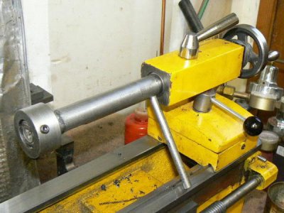
This is a simple tool for a simple task; I usually thread at 120 RPM (using pipe threading oil), pushing the tailstock by hand which is easy on my small Emco "Compact Eight". I've encountered no problems using hex or circular dies to produce full depth threads up to 1/2 inch diameter provided that the major diameter is turned to the low side of the "unified" thread standard tolerances. Most of my previous chasing work was nonferrous although after retirement, it is mostly mild steel.
FWIW, a rough rule of thumb for turning the major diameter is 2% below the nominal diameter. In other words, multiply the nominal diameter by 0.98 to obtain the diameter to which the rod must first be turned. For example, 1/2 - 20 UNF threads require that the nominal diameter be turned to .50 x .98 = .490 diameter before chasing the threads. This will minimize stress on the machine and wear on the die.
In use, the tailstock is not locked to the ways and is fed by hand (pushing on the rear of the tailstock). It will self-feed almost immediately after die engagement and only slight pressure on the rear of the tailstock is required to overcome friction and to prevent the taper from disengaging. It's only half as fast as a turret die head because the tool has to unthread (in reverse) over the work, instead of snapping open the dies when chasing is completed. (It's quicker to disengage the tailstock from the die and spin the die off by hand.)
I made this tool about ten years ago and each time that I use it, I wonder why it took so long before I thought of it. It is my next most often used tailstock tool, the drill chuck being the first and a dead center being the third. The 3/8 rod that prevents the tool from spinning in the tailstock has been modified since it was photographed to add a roller at the end so that the tool rolls along the vee way.
I've purchased several inexpensive die holders of different diameters for round dies; these are intended to be held in tailstock drill chucks, they are OK for their cost and for non-critical applications requiring short lengths of threads. (Most don't come with a means to prevent rotation and slippage so tack-welding a short rod to them is useful.) I think that these two came from Enco.
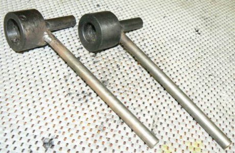
For electronic work - particularly microwave electronic work - small threads are the rule and threads from #0-80UNF (.060 major diameter) up to #4-40UNC (.112 major diameter) are the most common sizes in use at the component level. These are not easily single-pointed due to workpiece deflection so die-threading is the universally preferred method.
Hand Rotating The Spindle
This isn't really on topic but the thread chasing discussion reminded me that - when single-pointing external threads without a relief groove - I've been accustomed to rotating the spindle by hand for the last revolution or two. This is a personal routine, useful when forming tools or any other operation requiring a large amount of contact between workpiece and cutting tool is required, mainly because of the limitations of my small lathe.
A small diameter, shallow-depth, cross-drilled hole is also a neat way to terminate a single-pointed thread crisply - I believe this was illustrated in the original South Bend lathe book, many decades ago. By hand-rotating the spindle, it's possible to control the pull-out of the threading tool to any practical degree of accuracy, although the chip pile-up at the end of the cut may need to be removed after each pass (unless the cross-drill technique is used).
(Even simpler is starting the threading tool at the end of the thread, reversing the leadscrew rotation with the cutting tool upside-down and threading toward the tailstock. Because of the simple design of my smallest machine, an additional change gear is required to reverse leadscrew rotation so I have lost the habit of threading in reverse. I'm a thrifty guy, my little lathe has served me well for decades and old habits - if successful ones - aren't easily discarded when there is no production pressure. So the Emco 8 x 18 is still the most often-used lathe in my garage shop.)
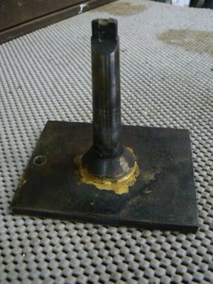
There are other operations where hand-rotating the lathe spindle can be useful so I made a simple tool that engages the spindle bore (to ease the procedure for my physical comfort). I must exercise care when rotating the spindle by hand with this tool for safety considerations. If the lathe was inadvertently powered up during the hand-rotation process (however unlikely) there probably wouldn't be a problem. The 1/2 ratchet wrench shown in the photo would free-wheel but if the lathe was accidentally powered up in REVERSE a very dangerous condition could result !
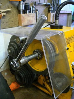
The tool used in the above photo to rotate the spindle was described in detail in a previous thread.
Reaming
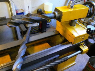
One way to utilize large reamers on a small lathe is to use a dead center in the tailstock, engaging the center in the shank of the reamer. (Chucking reamers are very convenient but aren't likely to be concentric with the spindle axis when secured in a drill chuck.) A lathe dog - or any similar expedient - bearing against a solid surface (like the inside surface of the ways), prevents the reamer from rotating as it is fed and guided by the dead center.
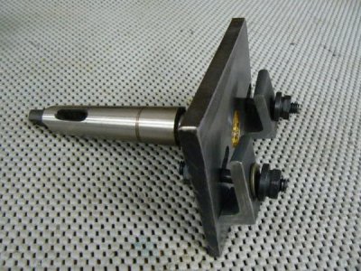
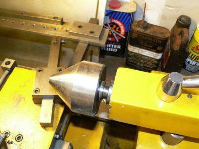
The tailstock center must be precisely aligned with the spindle centerline, throughout the travel required, if consistent, accurate results are expected. I made a simple tool to align, or confirm alignment, of a dead center in my tailstock. Aligning the tailstock takes less than a minute provided that a means of reference is available (the reason for making the tool).
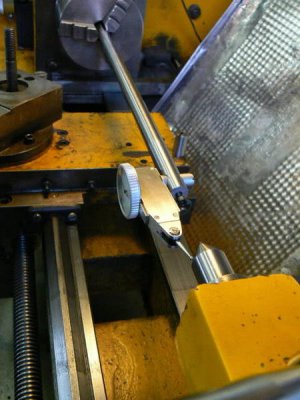
Note that chucking reamers have a very long shank - to accommodate slight misalignment between tailstock and workpiece. Engaging the leading edge of the reamer in the workpiece, with the tailstock snug but not fully clamped to the ways, the lathe is activated at a low spindle speed.
While feeding the reamer (pushing the tailstock by hand into the workpiece) the other hand is free to brush coolant on the reamer and to power down the lathe when the reamer reaches required depth. Which reminds me - not for the first time - that a foot switch would be a convenient feature for certain lathe operations - for small lathes - larger ones normally have foot-operated spindle clutches.
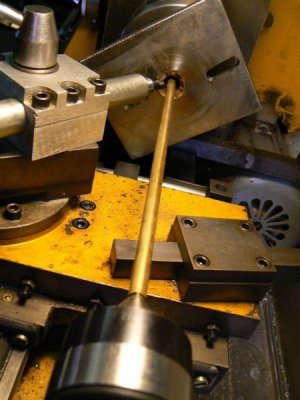
The setup below is similar - the dead center is engaged with the center hole in the chucking reamer shank and the ram is used to feed the reamer into the work. One additional step has been included to help the reamer start and run true. Just behind the reamer flutes, a small steady rest supports the shank, aligning it with the spindle axis.
The steady has been adjusted to center the reamer by indicating the reamer flutes with a DTI until the tool is concentric with the spindle. This setup takes a while to establish and isn't justified in most situations. In my opinion, taking the time to set up a reamer in this manner is wasted unless the pilot hole has been bored - a drilled pilot hole won't be coaxial with the spindle centerline and the reamer will try to follow the drilled hole.
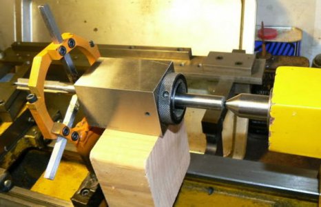
In the photo below, a reamer is prevented from rotation by securing the shank in a 5C collet block with a scrap of 4 x 4 resting on the ways of the lathe under it. Clearly there are dozens of ways to do this, depending upon tools and materials on hand and the time available.
In a hurry, one might be tempted to reach for a pair of vise-grips to clamp the shank of the reamer, resting the vise-grips on a scrap of wood laid across the ways. If I paid for a quality reamer, my inclination is to grip it in a manner that doesn't deform the shank. When chip load is light - and it always should be - substantial gripping force is not normally required.
Parts Two and Three to follow
(These are a collection of quick-fix anecdotes written several years ago and mainly intended for entertainment. Because readers vary in levels of experience and knowledge, I'm aiming at the novice. More experienced readers will have devised their own means for performing the operations that I've included. This is a post that I've been working on for a while and it is long-winded. I've tried to break it down into logical sections to avoid boredom.)
Introduction
The tailstock is a necessary but unglamorous feature of an engine lathe. We use it for drilling, reaming, tapping, centering and sometimes as a light arbor press but otherwise give little respect to the cast-iron appendage parked at the end of the ways. A bed-turret ? Now we're talking - THAT is something a home machinist can get excited about, but I get a lot of use from the tailstock.
The best machinists that I've worked for (or with) were characterized by invention in addition to their obvious knowledge and skill. The ability to configure an unconventional setup for a special task … to create a "fix" that reduces time, improves finish or precision … design a special tool for a specific job.
These often make the difference between a successful job shop run by an inventive owner or manager and one that goes belly-up after a year. (I worked in both environments, as a young man. Preferred the shop with a constant pay check, LOL, although frankly I didn't learn as much from the experience.)
After retirement and relocation from a major urban area, I established a home business. My work was engineering consultation, most often proposal work: specification analysis, creating a system architecture to provide the specified performance, estimation of development and production costs and sometimes detailed designs - all electronically transmitted to customers located in the San Francisco Bay Area.
Sounds nice, right ? Clean hands, nothing much to buy except copier paper, LOL. BUT sometimes a customer required measured performance data - prototypical "proof" of the key design aspects on which the system performance might depend. This involved making, assembling and testing microwave circuits comprised of fairly small parts, usually machined from non-ferrous materials (One bedroom of my house has been configured as an electronic test lab). Microwave "circuits" don't normally look like how most of us envision electronics.
Here are two examples of microwave circuits, photographed from a nineteen-sixties textbook. Note that the technology has come a LONG way beyond this and not just by decades ! One aspect of these circuits hasn't changed: the precision required. The two bandpass filters shown below were produced to locational tolerances of +/- .002 and thickness/cavity dimensions of +/- .0005 - fairly typical for state-of-the-art at that time.
These examples are representative of vertical mill operations but lathe operations were also required to produce microwave circuits to these tolerances. These examples were produced long before digital readouts and on manual machinery by skilled operators using techniques that were once common knowledge. (Sorry about the quality of the drawings - my digital camera is the copying machine.)

The following photo depicts the LARGEST single part that I've made in years:

Before relocating, my machine work was subcontracted to quick-reaction (= small) local shops. In my present semi-rural location, those resources weren't available so I had to tool up and resurrect old skills so that I could make the critical parts myself, LOL. The equipment in my small shop reflects my needs (small lathes, small mills, small welders, small inspection equipment, small everything)
But occasionally parts outside the normal capability or work envelope that the machine designers intended are required. I had some machinery and welding equipment before moving but required additional capability (mainly the two mills + tooling). Given my limited floor space - shared with a wood shop - unconventional solutions to some problems were suggested.
"Centerless" Operations
My first "real" machine tool was a used 6 x 18 Atlas lathe purchased around 1968, configured for rebuilding motors and generators. The keyless tailstock "commutator chuck" opened to 3/4 (or maybe an inch) diameter and had bronze jaws that resembled rounded vee-blocks. Journals of motor and generator shafts (or similar rotating workpieces) could be secured in the tailstock, free to rotate. The chuck functioned like a small steady rest but was much quicker to install, required minimal adjustment and produced good results - which gave me the following idea.
For working small diameter centerless ground shafting and the like, a convenient substitute for the commutator chuck (or for a center) is to turn a brass or bronze bushing that fits the tailstock drill chuck then bore/ream a running fit to the shaft to be centered/supported. (It's a good idea to cross-drill the bushing for an oil hole so that the work can be lubricated while turning if the operation involves substantial pressures or lengthy duration. This can also be a convenient means of ejecting short parts, with a jet of air.)
Eventually, I made rotating tailstock chuck using an old Jacobs 18N chuck, a hardened ball and a long oilite bushing. At first glance it looks like a conventional drill chuck. Looking closely, one can observe that the shank of the chuck is actually in two pieces. One of the three set screws that ride loosely in a groove can be seen. The purpose is to hold the two pieces together.

Note that this type of end support isn't normally used for long turning operations, where substantial amounts of taper might result from a slightly misaligned drill chuck. However the practice can be useful for short lengths, when requirements are not critical. In the example that follows, a length of ground shafting is supported so it is possible to fine-tune the tailstock alignment by sweeping the work with a DTI if greater precision is required. Those learning this craft should not be averse to changing tailstock alignment, which may be necessary for many operations - tapering for example - after which, re-centering will be required.
Shown below is a length of 7/16 diameter ground shafting supported in an oilite bushing that I was fortunate to have on hand - didn't have to make a bushing. The end of the shaft was de-burred and lightly sanded before insertion into the bushing. These are inexpensive and convenient to have around the shop - add a couple of them to each order from your normal tooling distributor and a respectable inventory will soon accumulate. The purpose of this particular operation, BTW, was to produce two "O" ring grooves near the end of the shaft. Drill bushings can be even more useful since they don't wear rapidly as do bronze bushings.

Incidentally, this can be a fairly good way to part off and collect short workpieces, instead of digging through the chip pan trying to find them - for occasional work. The bushing in the tailstock fully supports the parted off work so the little "nib" remaining on the work is almost non-existent. The tailstock is run up to the work so that the workpiece is partly enclosed in the bushing (it's unnecessary to clamp the tailstock to the ways - moving the tailstock by hand allows rapid engagement and withdrawal). A little slot or hole in the bushing allows ejecting the cutoff part, if required with a short blast of air.
It's helpful to grind the parting tool with a slight angle. Looking downward on the tool from above, the right edge (closest to tailstock) of the tool should part off the workpiece before the parting tool removes the nib from the stock held in the headstock chuck or collet. I tried to photograph this operation but the details were fuzzy; here's a sketch that might convey the shape of the parting tool better. As noted above, the stock needs to be de-burred before insertion into the support bushing but that should be an automatic reaction during parting operations.

Incidentally, if drill bushings are used in an application like the one shown above, cross-drilling holes for air ejection isn't practical. There are other possibilities for the HSM, the most common is the use of cheap diamond tooling in a die grinder (or Dremel tool). Both 1/8 and 1/4 shank diamond tools are available from most importers at throwaway prices (e.g. $6/dozen).
Measuring From The Tailstock
A simple measurement tool originally constructed for the vertical mill has also been useful in the lathe tailstock. Here's a description, a photo of the tool and the reason for making it. The tool consists of a 1/2 inch arbor (turned eccentric from 3/4 stock), bored to accept the stem of a travel indicator and slotted for clamping with a small socket head cap screw. (The shank must be clearance drilled about 1-1/4 inches deep so that the indicator spindle can travel up into the arbor.)

The original intent was to be able to adjust a workpiece, held in the milling vise - to a shallow angle with better precision than a spirit-level protractor head (when sine bar, gage blocks or angle plates weren't available or when time was limited). The process commences with the workpiece lightly clamped and adjusted to the approximate angle with the spirit level, then fine-tuned by gentle tapping with a soft hammer, monitoring progress with the indicator (it is helpful for the lowest end of the part to be supported in the vise with a small spacer or the end of a parallel, providing a "pivot point"):

The travel indicator is first zeroed at one end of the workpiece, then the "X" axis is offset by a known distance (determined by handwheel graduations or DRO) while holding the indicator spindle retracted by hand (so that it doesn't deflect from friction). Gently lowering the spindle of the indicator until it contacts the workpiece after the table has been offset, the indicator displacement is noted. (Although a "ball end" is shown in the photo, a flat end is OK for this application.)
The angle is determined by taking the arctangent (tan-1) of the two known distances. In the example above, the table has been displaced exactly 2.000 inches, according to the X axis dial count while the travel indicator shows a vertical displacement of .356 so the angle = tan-1 (.356/2.000) = 10.093 degrees.
[For the photographic example, an imported 10 degree angle plate was supported by a pair of imported parallels.
I didn't expect too much from the angle plate but thought that it should be more accurate than the measured 5.5 minutes (.093 degrees) of error. Removing the angle plate, I swept the parallels with the travel indicator and found an error of .0015 (the vise contributes to that error, too). If I subtract the error from the .356 previously measured, I get an angle of 10.05 degrees and an error of 3 minutes which is slightly better. After initially writing this, I looked at the catalog specs of the Enco angle plates and the measured angle is likely typical of the product.]
The example indicates the utility of a simple, inexpensive tool to determine angular accuracy (shallow angles) when one has neither sine bar nor gage blocks. The example also illustrates that imported tools, while seemingly good value for the money, need to be examined carefully when used in a setup that requires precision. (One of these days, I'll repeat the test using a sine bar and gage blocks, as an exercise.)
(Oh yeah … when the correct tangent reading is obtained, the vise is tightly clamped, checking one more time to be sure that the angle is correct.)
I've found other uses for the indicator/arbor … like setting stops on a drill press or precisely adjusting quill travel stops on a milling head. The indicating tool allows fairly accurate machine settings while installation/removal is quick and convenient. One of the most common uses is checking the level of work installed in the mill vise - slip the tool into a 1/2 collet and quickly run it front-to-back across the workpiece to check that it hasn't lifted enough in the vise to be problematic. (Any DTI can do this; it happens that the length is convenient for the purpose.)
Another application for this tool - similar to the last one - is setting a parting tool parallel with cross-slide travel. The measurement tool is installed into the collet/chuck in the headstock, and the cross-slide moved while the runout of the parting tool is observed with the indicator which rests along the top edge of the blade, adjusting the blade until there is no runout before clamping.

Sorry for the divergence - returning to topic, a convenient application for this device is in the lathe tailstock chuck. In above paragraphs discussing parting, I was reminded of how handy this measurement tool has been when parting off rods of various lengths in small quantities. The indicator is held in the tailstock and zeroed against the freshly parted face of the stock material (carriage is locked throughout all of the parting operations). Loosening the workholder (headstock chuck) slightly, the stock is extended until the indicator reading is the desired part length + the width of the parting tool. After tightening the 3-jaw chuck, the tailstock is retracted and the piece parted off to a precise length.

This is most useful when a number of parts of differing lengths are required and the tailstock is not required for supplementary operations such as drilling. If a number of parts of identical length are required, there are simpler means of performing the parting operation. In fact, extending that concept to its logical conclusion, a drill bushing secured in the chuck could provide both production stop and work support during parting.
Reviewing the sketch shown previously concerning the parting tool and the tailstock bushing supporting workpiece conveys the idea, I hope. (In addition to deburring the leading edge of the workpiece it's necessary to vacuum or blow out the bushing from time to time, freeing any small chips that may have inadvertently found their way inside.) Both operations can be performed simultaneously with a puff of shop air if a small hole is cross-drilled near the tailstock end of the bushing.

In short, an indicator tool like the one described, whose spindle is exactly in line with the 1/2 diameter shank, can be useful several times a day. Imagination is the only limit and I'm still finding applications for this simple device.
Tailstock As Drill Press
Securing, guiding and moving tools and workpieces has always required imagination combined with skill and experience. In cramped quarters, such as tiny workshops in small deepwater ships, sometimes only an engine lathe with a milling attachment can be accommodated so the drill press function is often performed by the lathe.

A friend was a machinist's mate on a U.S. Navy destroyer escort (during the Vietnam thing). I've enjoyed and learned from his anecdotal experiences of repair operations performed using a 10 inch South Bend, a milling attachment, welding equipment, hacksaw, chisels and files and his personal ingenuity. Some of the notes in this discussion resulted from conversations over a pint of beer or two.
Tapers
Short tapers can be easily cut using the compound-slide although there might be more unsupported tool overhang than we'd like. Long tapers are usually turned by offsetting the tailstock if the lathe has no taper attachment. Many newcomers to the craft don't care to disturb the alignment of their tailstock but only a few moments are required to re-align the ram by sweeping the Morse taper bore with a DTI held in the headstock (provided that the lathe ways are not overly worn and that the headstock is properly aligned).
Similarly, it's not difficult to offset the tailstock using a travel indicator to determine the proper offset (after first determining the length of the taper and solving for the tailstock offset). Use the appropriate trigonometric function of your pocket calculator to calculate the offset: tangent if the centerline length is known, sine if the tapered length is known. (If the travel indicator is left in place and not disturbed by the cutting operation, the tailstock can be returned to original position, after the taper has been turned, in less than a minute.)
Note that the "coincidence" of tailstock and spindle is a complex definition. Concentricity, axial/angular alignment of the two largely depends on where the tailstock is located, along the ways and how the machine is established on its foundation. This may not concern home machinists … because the tolerances we need to produce, the age of the machinery that we own and the lack of a production schedule allows us to take our time and produce acceptable fits with mating parts in the mechanisms that we design or modify. The alignment of headstock to tailstock to carriage has been discussed many times, most recently in this thread:
http://www.hobby-machinist.com/threads/two-collar-test-how-close-is-close-enough.31435/
In some setups, a hardened and ground steel ball is a better center than the standard 60 degree configuration provided that the cuts are not heavy. An expression frequently used when describing a tailstock offset to turn a taper is that the tailstock center "wallows out" the center-drilled hole, distorting the configuration. For shallow angles, this may not be critical but for larger angles a hardened ball can be a better idea.

In the above arrangement, a tapered arbor has been bored for a standard drill bushing (the drill bushing clamping method isn't shown but will be discussed later). By changing the size of the inexpensive drill bushing, various sizes of hardened balls may be accommodated, depending on the size of the workpiece. This is a versatile tool because drill bushings can also be used to support long workpieces (as described in the "centerless" paragraph above) when it's not possible to use a tailstock center. Both drill bushings and hardened balls can be readily and inexpensively obtained from your normal tooling distributor.

Many ingenious ideas have been implemented for offset taper turning. The most common seems to be replacing the normal tailstock center with a boring head. With a small 60 degree straight-shank center installed in the boring head, adjustment of the taper offset with precision is not difficult. Except for the large diameter fine pitch threads, it's not particularly challenging to make an arbor for the boring head with the appropriate taper for the lathe tailstock, keeping a couple of points in mind.
The possibility of the entire assembly rotating in the tailstock must be considered and some means to prevent this should probably be devised because the load imposed by the cutting tool may encourage torsional movement at the tailstock. Rotation isn't as likely as another problem: flexing of the center, which isn't good for accurate work. If the center is offset from the ram - as it will be when held in a boring head - the center will not be located along the load axis and deflection is unavoidable. It may or may not be a problem, depending on the accuracy required, material, cutting load and the load imposed by the tailstock ram.
Boring heads are designed to support centrifugal displacement due to their mass, the negligible weight of the cutting tool and a modest cutting load - they aren't intended to replace the function of the tailstock center, especially when supporting heavy weights combined with heavy DOC and feeds. I prefer the previous arrangement (tailstock ball center and offsetting the tailstock) because it avoids all of these problems.
As mentioned previously, adjusting tailstock offset and restoring it on center is not a difficult or lengthy procedure using a DTI. If one keeps a test "dumb-bell" handy, it's literally a matter of a minute or less. A test dumb-bell is a workpiece that has been turned between centers to align the lathe or the tailstock. If the two ends are exactly the same diameter - as they should be - then moving the carriage with DTI attached, comparing the two diameters allows quick, accurate centering of the tailstock. (This was discussed extensively in the post that was referenced above.)
Thread Chasing
One of the most useful tailstock applications for small lathes is chasing threads (small diameters and/or long lengths) although this is a function more often performed by turret lathes and speed lathes. The shop-made tool shown below passes over the carriage with adequate length to work up to the headstock. Short pieces of steel rod, salvaged from under the bandsaw, are welded to both ends of a length of steel pipe.
One end is turned to suit the tailstock taper and the other end is turned concentric in the same set-up. Two opposed slots are milled through the pipe, just behind the die head location, to allow clearing chips. I performed a primitive stress relief in the kitchen oven after welding and before finish machining the tool. (Three cycles from room temperature to 400 degrees F, allowing plenty of time to stabilize at temperature and plenty of time to cool.)
The headstock end is bored so that the die is centered on the lathe spindle when the tailstock is properly aligned with some clearance (provision is made for variability in inexpensive hex dies by including three adjustment screws). A crossbar is attached to the tailstock end, to prevent rotation and slipping in the tailstock. The tool produces threads many times more quickly than single-pointing, utilizing standard, inexpensive HSS hex dies for thread diameters up to 1/2. The adjustment screws included for centering the die are rarely used - I prefer a little float.

This is a simple tool for a simple task; I usually thread at 120 RPM (using pipe threading oil), pushing the tailstock by hand which is easy on my small Emco "Compact Eight". I've encountered no problems using hex or circular dies to produce full depth threads up to 1/2 inch diameter provided that the major diameter is turned to the low side of the "unified" thread standard tolerances. Most of my previous chasing work was nonferrous although after retirement, it is mostly mild steel.
FWIW, a rough rule of thumb for turning the major diameter is 2% below the nominal diameter. In other words, multiply the nominal diameter by 0.98 to obtain the diameter to which the rod must first be turned. For example, 1/2 - 20 UNF threads require that the nominal diameter be turned to .50 x .98 = .490 diameter before chasing the threads. This will minimize stress on the machine and wear on the die.
In use, the tailstock is not locked to the ways and is fed by hand (pushing on the rear of the tailstock). It will self-feed almost immediately after die engagement and only slight pressure on the rear of the tailstock is required to overcome friction and to prevent the taper from disengaging. It's only half as fast as a turret die head because the tool has to unthread (in reverse) over the work, instead of snapping open the dies when chasing is completed. (It's quicker to disengage the tailstock from the die and spin the die off by hand.)
I made this tool about ten years ago and each time that I use it, I wonder why it took so long before I thought of it. It is my next most often used tailstock tool, the drill chuck being the first and a dead center being the third. The 3/8 rod that prevents the tool from spinning in the tailstock has been modified since it was photographed to add a roller at the end so that the tool rolls along the vee way.
I've purchased several inexpensive die holders of different diameters for round dies; these are intended to be held in tailstock drill chucks, they are OK for their cost and for non-critical applications requiring short lengths of threads. (Most don't come with a means to prevent rotation and slippage so tack-welding a short rod to them is useful.) I think that these two came from Enco.

For electronic work - particularly microwave electronic work - small threads are the rule and threads from #0-80UNF (.060 major diameter) up to #4-40UNC (.112 major diameter) are the most common sizes in use at the component level. These are not easily single-pointed due to workpiece deflection so die-threading is the universally preferred method.
Hand Rotating The Spindle
This isn't really on topic but the thread chasing discussion reminded me that - when single-pointing external threads without a relief groove - I've been accustomed to rotating the spindle by hand for the last revolution or two. This is a personal routine, useful when forming tools or any other operation requiring a large amount of contact between workpiece and cutting tool is required, mainly because of the limitations of my small lathe.
A small diameter, shallow-depth, cross-drilled hole is also a neat way to terminate a single-pointed thread crisply - I believe this was illustrated in the original South Bend lathe book, many decades ago. By hand-rotating the spindle, it's possible to control the pull-out of the threading tool to any practical degree of accuracy, although the chip pile-up at the end of the cut may need to be removed after each pass (unless the cross-drill technique is used).
(Even simpler is starting the threading tool at the end of the thread, reversing the leadscrew rotation with the cutting tool upside-down and threading toward the tailstock. Because of the simple design of my smallest machine, an additional change gear is required to reverse leadscrew rotation so I have lost the habit of threading in reverse. I'm a thrifty guy, my little lathe has served me well for decades and old habits - if successful ones - aren't easily discarded when there is no production pressure. So the Emco 8 x 18 is still the most often-used lathe in my garage shop.)
There are other operations where hand-rotating the lathe spindle can be useful so I made a simple tool that engages the spindle bore (to ease the procedure for my physical comfort). I must exercise care when rotating the spindle by hand with this tool for safety considerations. If the lathe was inadvertently powered up during the hand-rotation process (however unlikely) there probably wouldn't be a problem. The 1/2 ratchet wrench shown in the photo would free-wheel but if the lathe was accidentally powered up in REVERSE a very dangerous condition could result !

The tool used in the above photo to rotate the spindle was described in detail in a previous thread.
Reaming
One way to utilize large reamers on a small lathe is to use a dead center in the tailstock, engaging the center in the shank of the reamer. (Chucking reamers are very convenient but aren't likely to be concentric with the spindle axis when secured in a drill chuck.) A lathe dog - or any similar expedient - bearing against a solid surface (like the inside surface of the ways), prevents the reamer from rotating as it is fed and guided by the dead center.
The tailstock center must be precisely aligned with the spindle centerline, throughout the travel required, if consistent, accurate results are expected. I made a simple tool to align, or confirm alignment, of a dead center in my tailstock. Aligning the tailstock takes less than a minute provided that a means of reference is available (the reason for making the tool).

Note that chucking reamers have a very long shank - to accommodate slight misalignment between tailstock and workpiece. Engaging the leading edge of the reamer in the workpiece, with the tailstock snug but not fully clamped to the ways, the lathe is activated at a low spindle speed.
While feeding the reamer (pushing the tailstock by hand into the workpiece) the other hand is free to brush coolant on the reamer and to power down the lathe when the reamer reaches required depth. Which reminds me - not for the first time - that a foot switch would be a convenient feature for certain lathe operations - for small lathes - larger ones normally have foot-operated spindle clutches.
The setup below is similar - the dead center is engaged with the center hole in the chucking reamer shank and the ram is used to feed the reamer into the work. One additional step has been included to help the reamer start and run true. Just behind the reamer flutes, a small steady rest supports the shank, aligning it with the spindle axis.
The steady has been adjusted to center the reamer by indicating the reamer flutes with a DTI until the tool is concentric with the spindle. This setup takes a while to establish and isn't justified in most situations. In my opinion, taking the time to set up a reamer in this manner is wasted unless the pilot hole has been bored - a drilled pilot hole won't be coaxial with the spindle centerline and the reamer will try to follow the drilled hole.
In the photo below, a reamer is prevented from rotation by securing the shank in a 5C collet block with a scrap of 4 x 4 resting on the ways of the lathe under it. Clearly there are dozens of ways to do this, depending upon tools and materials on hand and the time available.
In a hurry, one might be tempted to reach for a pair of vise-grips to clamp the shank of the reamer, resting the vise-grips on a scrap of wood laid across the ways. If I paid for a quality reamer, my inclination is to grip it in a manner that doesn't deform the shank. When chip load is light - and it always should be - substantial gripping force is not normally required.
Parts Two and Three to follow


