[How do I?] Make a 3 blade propellar hub

Cadillac

Registered
Registered
Joined
Mar 12, 2018
Messages
2,468
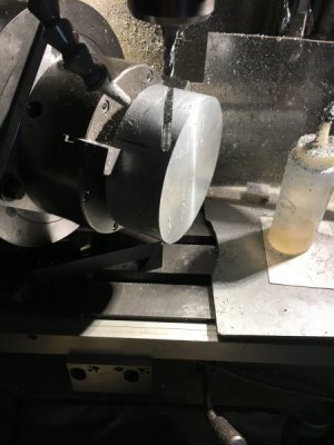
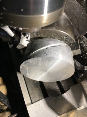
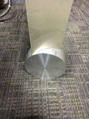
I've had a project for awhile that I'm finally trying to get done. I need to make a fan propellar for a ceiling fan. The hub needs to have three slots cut into it at a 25* angle. I have the material and layer it out. The kicker was I made a new backing plate for a 6"chuck to go on my RT to do the job and after trying to set up I can't see how to machine the piece. Here's what I have. 5" diameter 2" thick 25*slots.
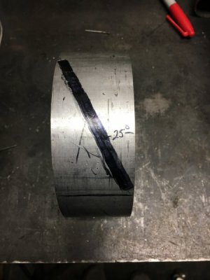
image.jpegimage.jpeg
So what I realized after setting up the way I thought to do it was. The piece mounted in the rotary table and the RT at a 25* angle to the table movement does NOT give me the motion to cut the slot. The only way I can see this happening is the table needs to drive the RT somehow. So as the table traverses slowly the RT is turning. Is this right? Can it be done easily? I need some advice please.
 
I've had a project for awhile that I'm finally trying to get done. I need to make a fan propellar for a ceiling fan. The hub needs to have three slots cut into it at a 25* angle. I have the material and layer it out. The kicker was I made a new backing plate for a 6"chuck to go on my RT to do the job and after trying to set up I can't see how to machine the piece. Here's what I have. 5" diameter 2" thick 25*slots.
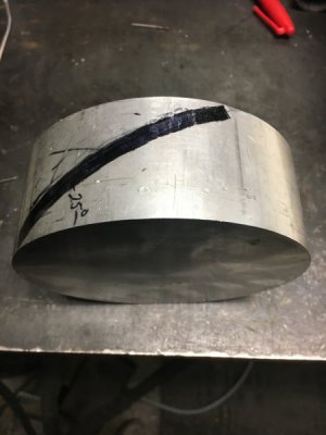
View attachment 282226View attachment 282227
So what I realized after setting up the way I thought to do it was. The piece mounted in the rotary table and the RT at a 25* angle to the table movement does NOT give me the motion to cut the slot. The only way I can see this happening is the table needs to drive the RT somehow. So as the table traverses slowly the RT is turning. Is this right? Can it be done easily? I need some advice please.
That is a job for a universal milling machine, where the table drives the dividing head through a train of gearing, I have a B&S mill with this feature.
 
Ideally you want the angle of the blade to be 34.5º at half the radius of the blade. In other words, a 24" diameter blade shoud have an attack angle of 34.48º 6 inches from the center of rotation. Higher closer to the hub, flatter farther from the hub.
 
If you could tolerate modifying the design a little, making the blades with a round tenon on the ends to fit three holes 120 degrees apart in the edge of the hub would allow you to rotate the blades to whatever attack angle you wanted. It makes for a slightly different looking hub, but it's very easy to set the angles. I made small wind turbine propellers this way. Not sure if you want to change your original concept plan though.

-frank
 
Thanks everyone for your quick responses. John I might be reaching out to you I knew I've seen this task done before.must be a interesting machine to watch run and a bear to set up? Tbredehoft my blades are 24" with a total diameter of 52-53". My plans are a low speed two fan setup with exposed belts driven off a single motor. I'm trying to reproduce a fanimation brewmasters fan but with a modern touch. I went off their attack angles for the blades. I want to move air with minimal blade speed. Francist that has also come to mind. Great minds think alike;) the only problem I have with that concept is I want it to look as streamline as possible. That's my last resort I have somewhat of a design for that already.
 
An easy job for a CNC mill with 4th axis capability....however....
 
Why would you not simply mill the groove at the angle straight across the round using the rotary table to index them 120 degrees apart?
Is there an internal clearance consideration?

The slow and dirty method for this is to attach a stylus to the quill that will follow the radius of the large diameter, this will require 2 hands operating the machine while milling, one to turn the X or Y axis handle and. the other to hold the Z axis handle against the stylus.

This method will leave artifacts at the start and end of the slot which may not be acceptable to a hobbyist.

If the artifacts are unacceptable a fifth axis will likely be required.
 
Yeah RJ I know :(guess what’s on my Christmas list. For the last five years:(i must not be good. :rolleyes:
Pwaller I thought about that also but the groove wouldn’t be the same depth which I guess would be only cosmetic. The blade would be relying on the bolts for alignment which idk but a pocket makes me feel better. At least that’s what I thought. That’s why I’m asking to see what’s others would do to accomplish this. More and more I’m thinking about this I’m leaning toward making six blade mounts with the peg. Still thinking.
 
Yeah RJ I know :(guess what’s on my Christmas list. For the last five years:(i must not be good. :rolleyes:
Pwaller I thought about that also but the groove wouldn’t be the same depth which I guess would be only cosmetic. The blade would be relying on the bolts for alignment

A pocket is exactly what I described, however it will not follow the radius of the OD and be far deeper in the center, a flat bottom pocket which is easily made on a manual machine.
Like so


If indeed there are constraints that limit the depth of the pocket such as components in the ID then this approach will not work.
This will also give a flat reference surface that will make producing the blades far simpler in the future.

If cosmetics is the major concern then spend the money and make it EXACTLY the way you want it, no other option exists.
 
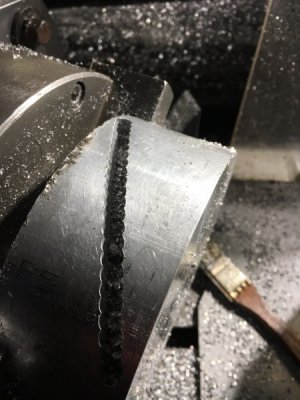
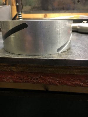
First off I wanna say thank you PWaller. Idk what you said or maybe the picture but it made me have the sight and juevos to do it. I mounted the RT back on the Bridgeport and set my angle 25*. I did a dry run first to make sure everything cleared. Then on the first slot I did the ends first to get the distance for the total slot to make sure it was centered on the hub. Once I got the width I needed it was just a lot of drilling with the endmill. After I get my depth I would step over .150 and repeat. Then traverse the table at max depth while raising and lower the z axis the radius of the hub. I had to go around twice the first endmill got me to about 5/8 depth and I changed to a 2" loc endmill and went to a final depth of 1" using the same drill and step over technique. With the 2" endmill I could only slot while raising the z axis. It would want to chatter if lower the z axis "going down while trying to cut". I'm very happy with the results I now have to copy it for the second one. Milling the slots took about 3 hours and very messy using air to evacuate chips. I set up a vacuum and it helps but with blowing and sucking it's kind of counter productive. Here's some shots of the operations. Thanks again PWaller:encourage:
image.jpegimage.jpeg
AFC5568A-30E7-4183-ADA7-5EF952E1AA79.jpeg
04F57D9F-E685-4921-9812-8849B1CA6E94.jpeg
923CBA71-1940-44EE-96B3-260C5A6D62FF.jpeg
 
Back
Top