- Joined
- Dec 29, 2012
- Messages
- 394
The Software needed
* Eagle CAD - download the free version of Eagle CAD from autodesk
* pcb-gcode - download the pcb-gcode Eagle CAD. Download here
Step 1: Setup the software
1. Setup Eagle following the instructions from autodesk.
2. Dowload PCB-GCode (Utility for EAGLE) and decompress it into a new folder
Step 2: Setting up PCB-GCODE in EAGLE
All files after decompressing pcb-gcode-3.6.2.4 are the following
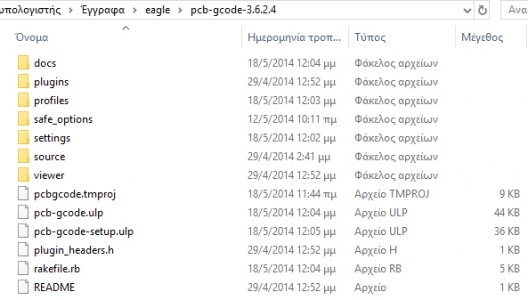
Search your computer, find the folder where EAGLE is installed and open it. In there there is a folder named ULP. I copy everything that is in the folder pcb-gcode-3.6.2.4 and paste it in ULP folder.
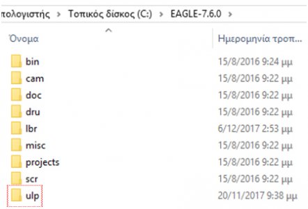
When you click ULP button on EAGLE toolbox it opens the ULP folder and asks which file to open. Scroll down and open pcb-gcode setup and make all settings needed.
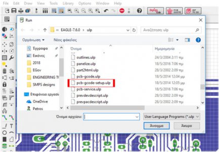
First TAB is the Generation options:
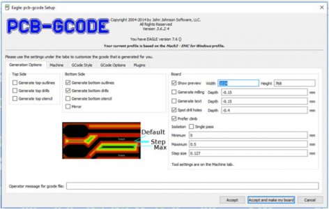
Generation Options settings
These are basic settings for what types of Tool Paths you want to create and how detailed they should be.
The Top Side and Bottom Side setting will depend on whether you will be making a single or double sided PCB.
Show preview is always good to have checked so you can see that everything turned out how you expected it to. As my vision is not what it used to be I like to keep the Width and Height at 1024 x 768.
Generate milling is used for cutting the PCB outline. I DO NOT USE IT AT THE MOMENT
Generate text is used to engrave text onto your PCB. Only text that uses the Vector font and is on EAGLE Layer 46 Milling will be included in the G-Code. I DO NOT USE IT AT THE MOMENT
Spot drill holes will make small marks wherever a hole will be drilled after the trace isolation cuts are made. This helps the drill bits get nice and centered when drilling the holes.
Prefer climb sets the overall direction that the CNC Mill should move in for milling. I do prefer to have my mill do climbing cuts and that is why I have this option checked.
Isolation lets you control how the software will outline each of your traces. These settings depend heavily on the tip diameter of the end mill or engraving bit that will be used to outline your traces.
Single pass only does one outline around your traces.
Minimum lets you set the smallest amount of space that your end mill or engraving bit can cut. 0 inches to ensure that every trace is outlined at least once to isolate it.
Maximum sets the maximum spacing that you want cut around each trace. This will determine how many times the CNC mill will outline each trace.
Step size tells the software how much space your want between isolation passes. If you are using an end mill, this should be about 40% of the tip diameter of your bit. 0.004 in. Engraving bits can use a step size equal to the flat diameter of the bit because it is tapered and that makes the cuts wider as it goes deeper into the carrier board.
Next is TAB is Machine:
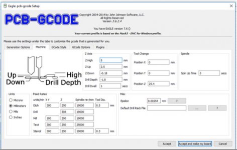
Machine settings control how fast the CNC Mill will cut, details about your cutting tools, and the units of measurement you wish to use.
Z Axis lets you set some standardized milling depths.
Z High sets the safe height for the mill to move around without running into anything like your clamps. 0.5 inches is a safe bet for this.
Z Up is the safe height for movements from one cut to the next. I set this to 0.1 inches.
Z Down sets the cutting depth for the trace isolation. This should be set to go just below the copper layer. I use -0.007 inches.
Drill Depth should be set to about 0.005 inches below the thickness of your carrier board. So if your carrier board is 0.062 inches, you would set this option to -0.067 inches.
Drill Dwell tells the machine how long it should wait before pulling the drill bit back out of a newly drilled hole. About 1 second is good to get a cleanly drilled hole.
The Tool Change options don’t work so well, but I put 0 in for Position X and Y and 1 inch for Position Z.
Spin up time is used to set the time it takes for the spindle to get to full speed once it is turned on. If your CNC Mill does not automatically turn your spindle or router on and off, don’t worry about this setting.
Units tells the software what unit of measurement you want to use for everything.
Feed Rates lets you set the optimal speed that your CNC Mill will move while cutting and drilling. This is very important to prevent your bits from breaking and getting clean cuts.
Etch settings are used for the trace isolation outlines
Drill sets the drilling speed.
Mill settings are used for cutting out the PCB when finished. I DO NOT USE IT AT THE MOMENT.
Text I DO NOT USE IT AT THE MOMENT.
Stencil I DO NOT USE IT AT THE MOMENT.
Click on the ? buttons if you really want to know what the Misc options are, but they are not important for what we are doing.
Next Tab is G-code Style: I choose Mach3
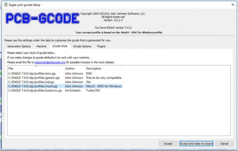
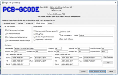
Next Tab is Gcode options: select use simple drill code!
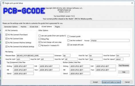
The GCode Options window
NC File Comments PCB-GCode puts some rather long notes into the G-Code that it generates. This might result in errors when you send the G-Code file to CNC Mill. Un-checking all of the NC File Comments options will fix this issue.
Under Other Options, I only check the Do tool change with zero step and Use simple drill code options. The Format should be set to N%05d by default.
File Naming can be changed if you want to, but I would just leave it alone.
Next Tab is plugins: I only click the button “Accept and make my board”
Next the preview screen will pop up: A red cross marks the point of origin (If it is at a distance from the board you designed, like here, you must go back to EAGLE board and move the board closer to 0,0 (point of origin)
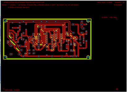
The proper alignment should be like this
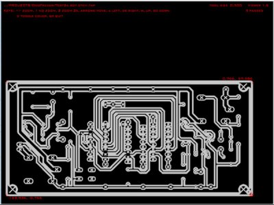
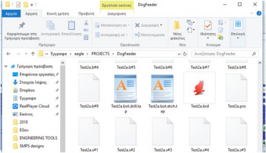
In the folder where EAGLE saves the project you are working there will be two files with the extension “.tap” that have been created by this procedure. One of them is named «name.bot.drill.tap» and the other «name.bot.etch.tap». I named my project “test2a” so the two gcode files are named accordingly.
Step 3: Design a Board With Eagle
EAGLE is free to use for making small PCBs up to 8cm^2. I assume that you already have EAGLE installed and that you know how to use it for creating a PCB design. If this is not the case, I recommend checking out any one of the many tutorials that people have made for EAGLE like this one.
Use Eagle CAD DRC to Enforce Design Limitations
1. In Eagle CAD, select 'Tools->DRC->Clearance'
2. Set all of the 'Different Signals' clearances to a value larger than your engraving tool (12mil seems to work for a 30deg V-Bit)
3. If you already have a board designed, select 'Check' to see what parts of your board may be too close together to isolate
Step 4: Make the G-Code for the Board
Use pcb-gcode to generate G-Code from Eagle CAD
1. Open your board design in Eagle CAD
2. From the Eagle CAD click ULP button select pcb-gcode setup.ulp and run
3. The pcb-gcode dialog will pop up.
4. On the 'Generation Options' tab, select 'Generate bottom outlines', 'Generate bottom drills' 'Show preview', Spot drill holes, Prefer climb
5. On the 'Machine' tab, set 'Spindle Up Time' to 3 and set the feed rates to 300mm/min
6. Set 'Z High' to 12mm, 'Z Up' to 3mm, 'Z Down' to -0.08mm
7. Use calipers to determine the thickness of your board and enter that value plus 0.1mm or so for 'Drill Depth'
8. On the 'GCode Style' tab, select 'Mach3 - EMC for Windows'
9. On the 'GCode Options' tab, select all of the 'NC File Comments' options as well as 'Do tool change with zero step'
10. Click 'Accept and make my board'
11. An image view window will pop up and display what will be etched. pcb-gcode will join signals that are too close so look at the image carefully to make sure that all signals are properly isolated.
Step 5: Mill!
Load the Gcode
Click 'Cycle Start' on the Mach3 Screen to begin engraving
Use the spindle speed control to adjust the spindle speed to something appropriate. If the speed is too low you may see ragged chips of copper. If the speed is too high you may see copper being finely polished instead of cut.
Step 6: Drill!
1. When milling has finished, raise the spindle.
2. Click 'Go To Zero' on the Mach3 Program Run tab
3. Use the page up key to raise the spindle again
4. Remove the engraving bit from the spindle
5. Chuck an appropriately small carbide tipped drill bit
6. Use 'File->Load GCode' within Mach3 to load your drilling G-Code (named something.bot.drill.tap)
7. Use the page down key to lower the spindle until it is just barely touching the work piece
8. Click 'Zero Z' on Mach3
9. Click 'Cycle Start' on Mach3 to begin drilling
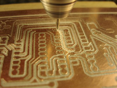
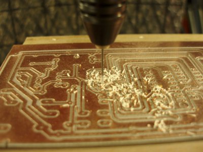
There is my first effort using the above steps.
Milling
Drilling
Final pcb
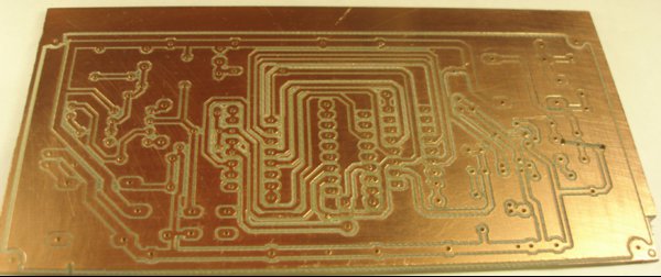
Not bad for the first pcb on the mill!!
Good Luck!
Petros
* Eagle CAD - download the free version of Eagle CAD from autodesk
* pcb-gcode - download the pcb-gcode Eagle CAD. Download here
Step 1: Setup the software
1. Setup Eagle following the instructions from autodesk.
2. Dowload PCB-GCode (Utility for EAGLE) and decompress it into a new folder
Step 2: Setting up PCB-GCODE in EAGLE
All files after decompressing pcb-gcode-3.6.2.4 are the following

Search your computer, find the folder where EAGLE is installed and open it. In there there is a folder named ULP. I copy everything that is in the folder pcb-gcode-3.6.2.4 and paste it in ULP folder.

When you click ULP button on EAGLE toolbox it opens the ULP folder and asks which file to open. Scroll down and open pcb-gcode setup and make all settings needed.

First TAB is the Generation options:

Generation Options settings
These are basic settings for what types of Tool Paths you want to create and how detailed they should be.
The Top Side and Bottom Side setting will depend on whether you will be making a single or double sided PCB.
Show preview is always good to have checked so you can see that everything turned out how you expected it to. As my vision is not what it used to be I like to keep the Width and Height at 1024 x 768.
Generate milling is used for cutting the PCB outline. I DO NOT USE IT AT THE MOMENT
Generate text is used to engrave text onto your PCB. Only text that uses the Vector font and is on EAGLE Layer 46 Milling will be included in the G-Code. I DO NOT USE IT AT THE MOMENT
Spot drill holes will make small marks wherever a hole will be drilled after the trace isolation cuts are made. This helps the drill bits get nice and centered when drilling the holes.
Prefer climb sets the overall direction that the CNC Mill should move in for milling. I do prefer to have my mill do climbing cuts and that is why I have this option checked.
Isolation lets you control how the software will outline each of your traces. These settings depend heavily on the tip diameter of the end mill or engraving bit that will be used to outline your traces.
Single pass only does one outline around your traces.
Minimum lets you set the smallest amount of space that your end mill or engraving bit can cut. 0 inches to ensure that every trace is outlined at least once to isolate it.
Maximum sets the maximum spacing that you want cut around each trace. This will determine how many times the CNC mill will outline each trace.
Step size tells the software how much space your want between isolation passes. If you are using an end mill, this should be about 40% of the tip diameter of your bit. 0.004 in. Engraving bits can use a step size equal to the flat diameter of the bit because it is tapered and that makes the cuts wider as it goes deeper into the carrier board.
Next is TAB is Machine:

Machine settings control how fast the CNC Mill will cut, details about your cutting tools, and the units of measurement you wish to use.
Z Axis lets you set some standardized milling depths.
Z High sets the safe height for the mill to move around without running into anything like your clamps. 0.5 inches is a safe bet for this.
Z Up is the safe height for movements from one cut to the next. I set this to 0.1 inches.
Z Down sets the cutting depth for the trace isolation. This should be set to go just below the copper layer. I use -0.007 inches.
Drill Depth should be set to about 0.005 inches below the thickness of your carrier board. So if your carrier board is 0.062 inches, you would set this option to -0.067 inches.
Drill Dwell tells the machine how long it should wait before pulling the drill bit back out of a newly drilled hole. About 1 second is good to get a cleanly drilled hole.
The Tool Change options don’t work so well, but I put 0 in for Position X and Y and 1 inch for Position Z.
Spin up time is used to set the time it takes for the spindle to get to full speed once it is turned on. If your CNC Mill does not automatically turn your spindle or router on and off, don’t worry about this setting.
Units tells the software what unit of measurement you want to use for everything.
Feed Rates lets you set the optimal speed that your CNC Mill will move while cutting and drilling. This is very important to prevent your bits from breaking and getting clean cuts.
Etch settings are used for the trace isolation outlines
Drill sets the drilling speed.
Mill settings are used for cutting out the PCB when finished. I DO NOT USE IT AT THE MOMENT.
Text I DO NOT USE IT AT THE MOMENT.
Stencil I DO NOT USE IT AT THE MOMENT.
Click on the ? buttons if you really want to know what the Misc options are, but they are not important for what we are doing.
Next Tab is G-code Style: I choose Mach3

Next Tab is Gcode options: select use simple drill code!

The GCode Options window
NC File Comments PCB-GCode puts some rather long notes into the G-Code that it generates. This might result in errors when you send the G-Code file to CNC Mill. Un-checking all of the NC File Comments options will fix this issue.
Under Other Options, I only check the Do tool change with zero step and Use simple drill code options. The Format should be set to N%05d by default.
File Naming can be changed if you want to, but I would just leave it alone.
Next Tab is plugins: I only click the button “Accept and make my board”

Next the preview screen will pop up: A red cross marks the point of origin (If it is at a distance from the board you designed, like here, you must go back to EAGLE board and move the board closer to 0,0 (point of origin)

The proper alignment should be like this

In the folder where EAGLE saves the project you are working there will be two files with the extension “.tap” that have been created by this procedure. One of them is named «name.bot.drill.tap» and the other «name.bot.etch.tap». I named my project “test2a” so the two gcode files are named accordingly.

Step 3: Design a Board With Eagle
EAGLE is free to use for making small PCBs up to 8cm^2. I assume that you already have EAGLE installed and that you know how to use it for creating a PCB design. If this is not the case, I recommend checking out any one of the many tutorials that people have made for EAGLE like this one.
Use Eagle CAD DRC to Enforce Design Limitations
1. In Eagle CAD, select 'Tools->DRC->Clearance'
2. Set all of the 'Different Signals' clearances to a value larger than your engraving tool (12mil seems to work for a 30deg V-Bit)
3. If you already have a board designed, select 'Check' to see what parts of your board may be too close together to isolate
Step 4: Make the G-Code for the Board
Use pcb-gcode to generate G-Code from Eagle CAD
1. Open your board design in Eagle CAD
2. From the Eagle CAD click ULP button select pcb-gcode setup.ulp and run
3. The pcb-gcode dialog will pop up.
4. On the 'Generation Options' tab, select 'Generate bottom outlines', 'Generate bottom drills' 'Show preview', Spot drill holes, Prefer climb
5. On the 'Machine' tab, set 'Spindle Up Time' to 3 and set the feed rates to 300mm/min
6. Set 'Z High' to 12mm, 'Z Up' to 3mm, 'Z Down' to -0.08mm
7. Use calipers to determine the thickness of your board and enter that value plus 0.1mm or so for 'Drill Depth'
8. On the 'GCode Style' tab, select 'Mach3 - EMC for Windows'
9. On the 'GCode Options' tab, select all of the 'NC File Comments' options as well as 'Do tool change with zero step'
10. Click 'Accept and make my board'
11. An image view window will pop up and display what will be etched. pcb-gcode will join signals that are too close so look at the image carefully to make sure that all signals are properly isolated.
Step 5: Mill!
Load the Gcode
Click 'Cycle Start' on the Mach3 Screen to begin engraving
Use the spindle speed control to adjust the spindle speed to something appropriate. If the speed is too low you may see ragged chips of copper. If the speed is too high you may see copper being finely polished instead of cut.
Step 6: Drill!
1. When milling has finished, raise the spindle.
2. Click 'Go To Zero' on the Mach3 Program Run tab
3. Use the page up key to raise the spindle again
4. Remove the engraving bit from the spindle
5. Chuck an appropriately small carbide tipped drill bit
6. Use 'File->Load GCode' within Mach3 to load your drilling G-Code (named something.bot.drill.tap)
7. Use the page down key to lower the spindle until it is just barely touching the work piece
8. Click 'Zero Z' on Mach3
9. Click 'Cycle Start' on Mach3 to begin drilling
There is my first effort using the above steps.
Milling

Drilling

Final pcb

Not bad for the first pcb on the mill!!
Good Luck!
Petros

