- Joined
- Sep 5, 2013
- Messages
- 3,720
Not sure if this will fit into one post or not but we’ll see.
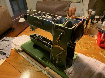
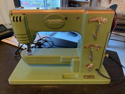
A couple months ago I spied another interesting machine on our local used marketplace and of course dragged it home. It’s a Swiss-made “Turissa” which I’m not going say is super-rare but it’s definitely uncommon. At least in North America anyway.
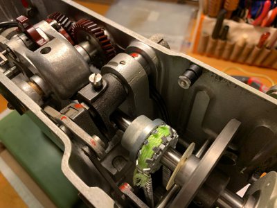
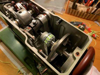
When I got it home and started going over it I suddenly realized it was missing its timing belt. This is pretty important — it links the main driving shaft on top to the lower bobbin and feed mechanisms down below. — and without it the machine can’t sew. And then I realized something even more weird — the belt was still there, just in a much-altered state.
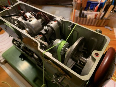
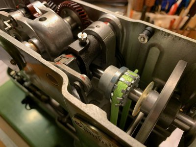
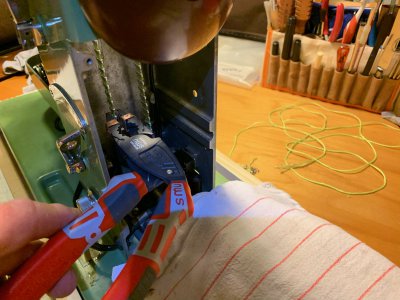
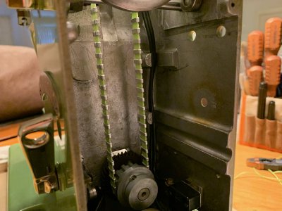
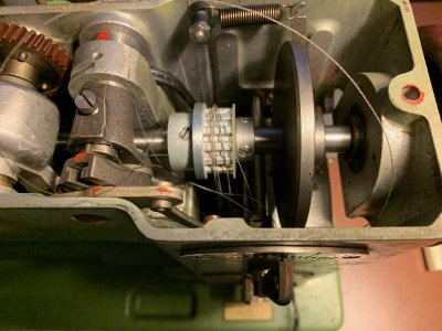
This is what’s left of the original cogged belt: just a few wraps of the fine reinforcement wire that formed the inner core of whatever synthetic they had made the rest of the belt from. That material had bizarrely degraded into small pockets of granular dust down the bottom of the chassis leaving only the wires grinning like the Cheshire Cat smile over the pulleys.
So what to do? Parts as might be imagined are few and far between (early 1950’s machine) and even then why would I want an original belt if it was going to turn to dust too? To make matters more complicated, the pitch or spacing of the cogs on the pulleys didn’t match up with any of the standard belt sizes I could find today. I don’t know if it pre-dated the standardization of belts or whether it was just one of those proprietary things, but regardless there was not one to be had that was going to fit. As a bit of a sidebar here, I did find one later in my salvage drawer that belonged to an old IBM electric typewriter of about the same vintage and it had the same pitch, so I’m guessing at one time it may have been a common belt pattern but not so now.
So after much head scratching and napkin designing I came up with a list of options on how I might make one. I have a couple of other machines that use a belt made from cord wraps held together with wire cleats (this was a very common method) and that’s the option I chose as my first attempt.
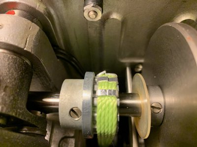
The string or cord was easy enough: some nylon builder’s line from the local Canadian Tire seemed about the right weight to me so I went with that. For the cleats themselves I worked through a number of material choices and techniques to ultimately settle on 6061 aluminum. More experimenting to get the right amount of stiffness and still be bendable enough for me to crimp in place but eventually I had what looked promising. Here’s a test fit with some sample string in place but cleat length not quite nailed down yet.
Once I had my sizes figured I just had to come up with about sixty-five of the little suckers so I decided to run them in two cards that would give me consistent sizing but be easy to separate. Here’s a photo of milling the crossways lengths using an 0.028” slitting saw. The blade is shy of the platen by about ten-thousandths so that the card stayed in one piece for all the cuts.
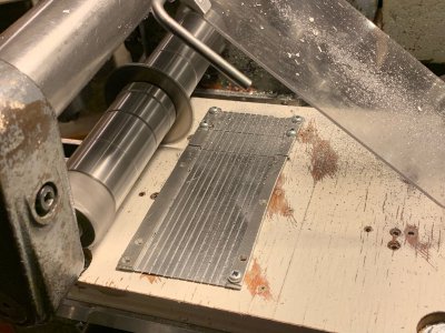
And here’s what happens when you think you have enough hold-down points but really don’t…
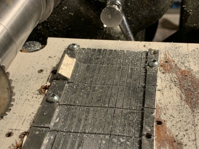
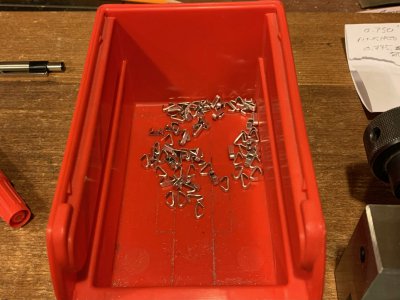
Once the aluminum was all scored I could break off the individual cleats for filing and finishing. I wanted them accurate and fairly close fitting as they would provide my register to get the spacing right. I could file five in the space of fifteen minutes, so after a few hours I was done. They are slightly trapezoidal in cross-section to slip in and out of the pulley slots nicely.
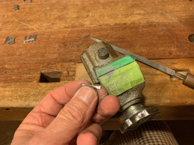
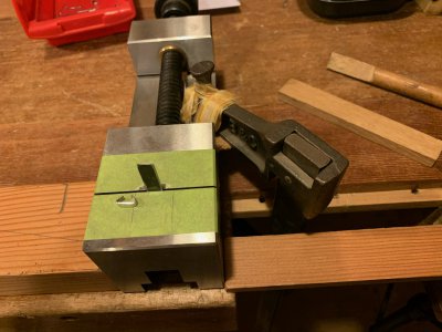
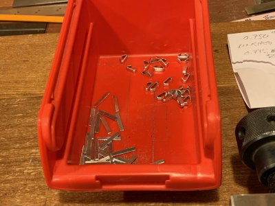
Assembling the test belt was definitely easier if the cleats were somewhat formed in advance so I made a little setup to get a decent pre-crimp starter shape. It’s just a slip of metal filed to the right width and held vertical in the vise so that the blank can be bent around it. I used the two hardwood sticks for that — worked great.
Part 2 to follow….
A couple months ago I spied another interesting machine on our local used marketplace and of course dragged it home. It’s a Swiss-made “Turissa” which I’m not going say is super-rare but it’s definitely uncommon. At least in North America anyway.

When I got it home and started going over it I suddenly realized it was missing its timing belt. This is pretty important — it links the main driving shaft on top to the lower bobbin and feed mechanisms down below. — and without it the machine can’t sew. And then I realized something even more weird — the belt was still there, just in a much-altered state.
This is what’s left of the original cogged belt: just a few wraps of the fine reinforcement wire that formed the inner core of whatever synthetic they had made the rest of the belt from. That material had bizarrely degraded into small pockets of granular dust down the bottom of the chassis leaving only the wires grinning like the Cheshire Cat smile over the pulleys.

So what to do? Parts as might be imagined are few and far between (early 1950’s machine) and even then why would I want an original belt if it was going to turn to dust too? To make matters more complicated, the pitch or spacing of the cogs on the pulleys didn’t match up with any of the standard belt sizes I could find today. I don’t know if it pre-dated the standardization of belts or whether it was just one of those proprietary things, but regardless there was not one to be had that was going to fit. As a bit of a sidebar here, I did find one later in my salvage drawer that belonged to an old IBM electric typewriter of about the same vintage and it had the same pitch, so I’m guessing at one time it may have been a common belt pattern but not so now.
So after much head scratching and napkin designing I came up with a list of options on how I might make one. I have a couple of other machines that use a belt made from cord wraps held together with wire cleats (this was a very common method) and that’s the option I chose as my first attempt.
The string or cord was easy enough: some nylon builder’s line from the local Canadian Tire seemed about the right weight to me so I went with that. For the cleats themselves I worked through a number of material choices and techniques to ultimately settle on 6061 aluminum. More experimenting to get the right amount of stiffness and still be bendable enough for me to crimp in place but eventually I had what looked promising. Here’s a test fit with some sample string in place but cleat length not quite nailed down yet.

Once I had my sizes figured I just had to come up with about sixty-five of the little suckers so I decided to run them in two cards that would give me consistent sizing but be easy to separate. Here’s a photo of milling the crossways lengths using an 0.028” slitting saw. The blade is shy of the platen by about ten-thousandths so that the card stayed in one piece for all the cuts.

And here’s what happens when you think you have enough hold-down points but really don’t…

Once the aluminum was all scored I could break off the individual cleats for filing and finishing. I wanted them accurate and fairly close fitting as they would provide my register to get the spacing right. I could file five in the space of fifteen minutes, so after a few hours I was done. They are slightly trapezoidal in cross-section to slip in and out of the pulley slots nicely.

Assembling the test belt was definitely easier if the cleats were somewhat formed in advance so I made a little setup to get a decent pre-crimp starter shape. It’s just a slip of metal filed to the right width and held vertical in the vise so that the blank can be bent around it. I used the two hardwood sticks for that — worked great.


Part 2 to follow….

