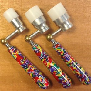
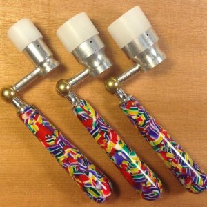
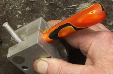
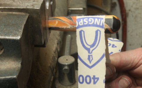
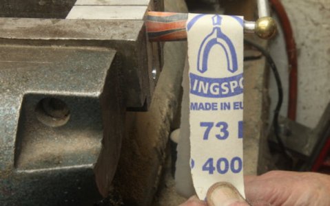
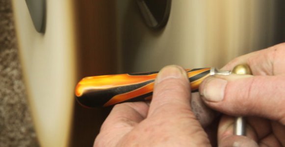
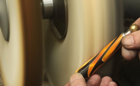
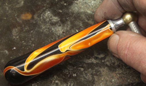
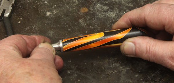
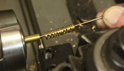
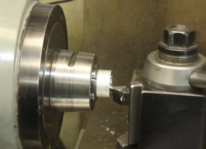
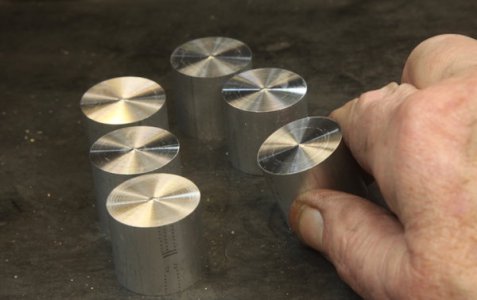
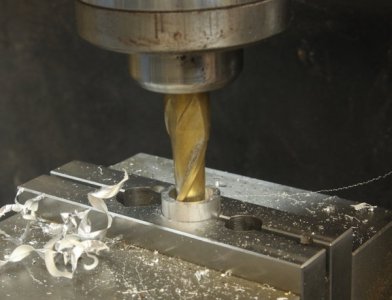
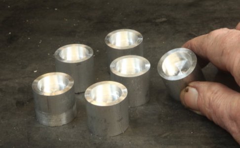
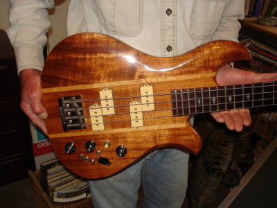
Finally got around to taking some photos of my process as I make some of my string winding cranks. Here's one with a koa handle:
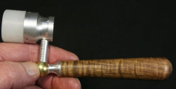
These cranks feature a soft head made of low density polyethylene, an angle of 83-degrees to simulate wrist rotation, and a solid bearing in the handle.
Interestingly, one of the first questions I get about them is, "How do you achieve that angle?" So, I'll start the description with that in mind. . .
The only commercially made part is the little brass ball, which I drill almost all the way through with a 6.4mm drill that gives me a .252: hole, making for a nice sliding fit for a 1/4" precision ground aluminum rod:
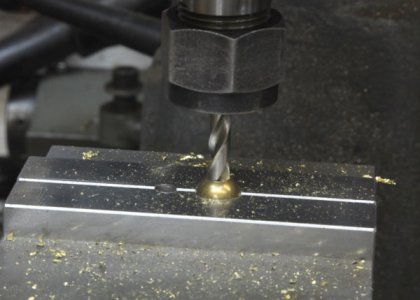
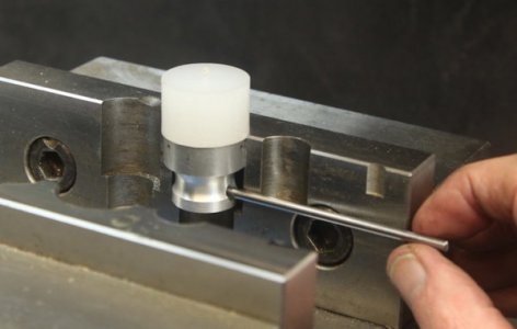
Here, I'm using my tiny Rusnok milling machine. I have the ball set into a matching cavity I milled by plunging with sa 1/2" ball end mill into the steel soft jaws on my old 4" Kurt vise. By the way, I get my soft jaws for vises and chucks from monsterjaws.com - no affiliation - they sell CNC made jaws for about what I'd pay for raw material.
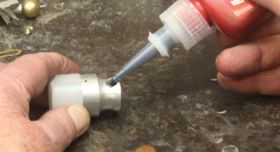
A single drop of Loctite 609 green bearing retaining compound goes into the hole:
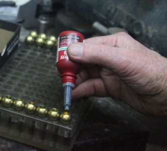
Then the 1.60" long 1/4" aluminum rod:
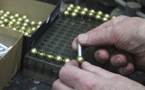
A gentle but quick squish in the bench vise forces the green compound right out so I can be assured of complete coverage:
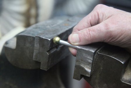
It takes overnight for a complete cure, but it sets up in seconds so it can be handled with no chance of loosening.
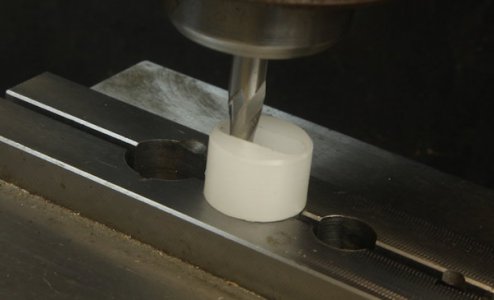
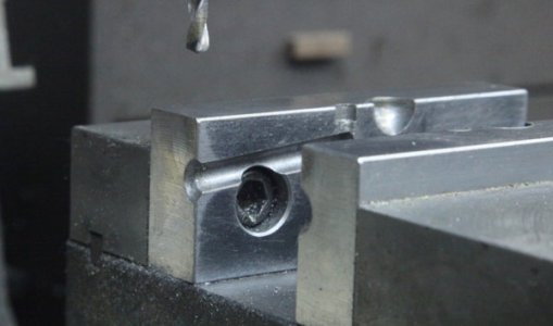
Here's another view of Kurt's soft jaws, showing the recess I milled to hold the completed assembly for drilling that 83-degree angle hole:
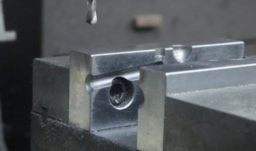
The little crank arm fits right in there:
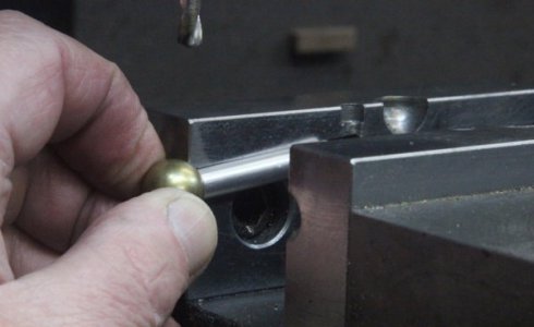
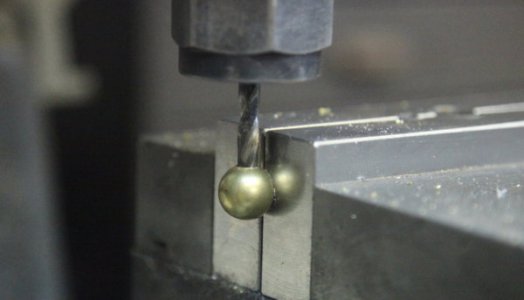
A #12 drill gives me about .0015" clearance for a slip fit on my 3/16" diameter steel bearing shaft:
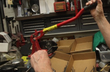
My vise mounted bolt cutter chops off sections of 3/16" steel rod, and they shoot all over the place, so I position a few shallow boxes to catch them so I don't actually have to clean off a section of my bench:
Of course, the bolt cutter leaves nasty deformed cut ends, so it's off to the 2x72 belt grinder for a quick bit of squaring up and chamfering:
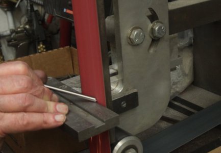
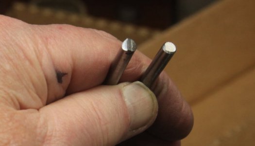
The cut end on the left becomes the nice smooth one on the right in almost no time:
Then, it's time for another drip of the green Loctite to secure the bearing shaft:
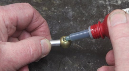
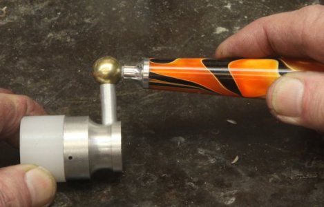
So, here's that 83-degree elbow, after all:
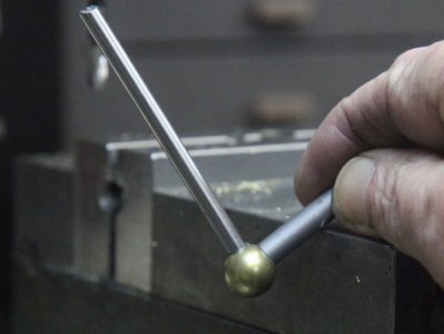
I milled halfway through one so you could see the inside, where the smaller steel shaft runs right through the ball and the 1/4" crank arm, for a solid joint assembly:
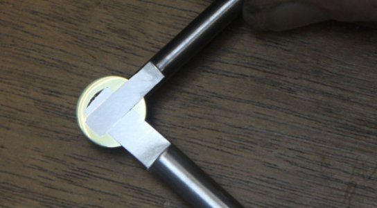
A few years ago I had a steel stamp made so I could mark my stuff, and for this project, I made up a special little fixture that holds it with some inset neodymium magnets while I whack it with my classic B.F.H. to get a good impression, right on center:
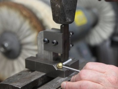
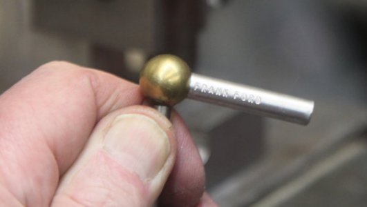
As they'd say in a previous century, "None Genuine Without This Brand."
NEXT UP IS THE ALUMINUM BEARING FOR THE HANDLE . . . . . . .
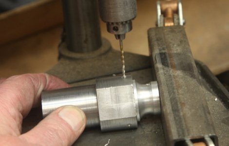
The handle bearing starts out as a 2.25" long piece of 1/2" 6061 aluminum rod, and I drill through it with a number 12 drill bit:
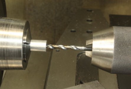
That's not the drill bit I actually use - it's a staged photo. I really use a parabolic drill for better chip clearance, and to try to keep things straight and on center, I drill halfway from each end. The #12 bit gives me just enough clearance for the bearing shaft and lubrication.
One end gets a touch with a 90-degree countersink to butt up against the brass ball:
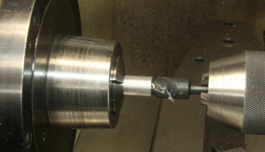
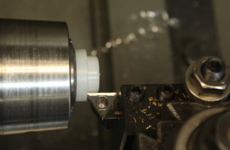
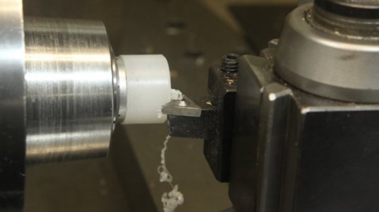
Flipping it around, I turn down the outside of the shaft to 5/16." Gripping the last half inch in the collet, I can just manage to turn down the 1.75" I need without supporting the outboard end:
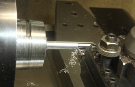
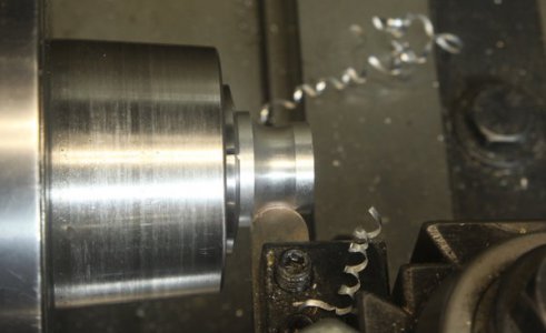
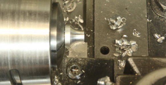
Switching to a 5/16" collet and gripping up close, I use a 1/4" radius form tool to shape the end of the bearing:
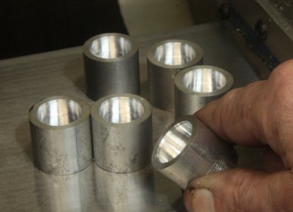
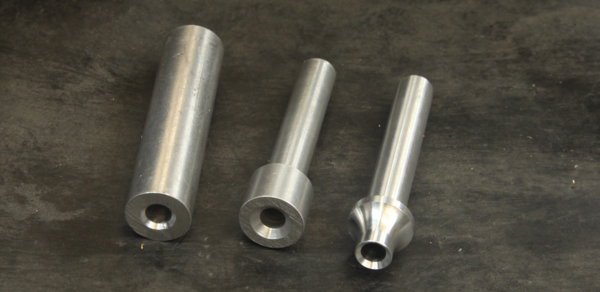
Here's a shot of the stages in making the bearing:
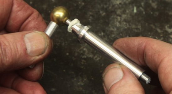
Painting on a thick layer of white lithium grease, I squidge the bearing onto the shaft:
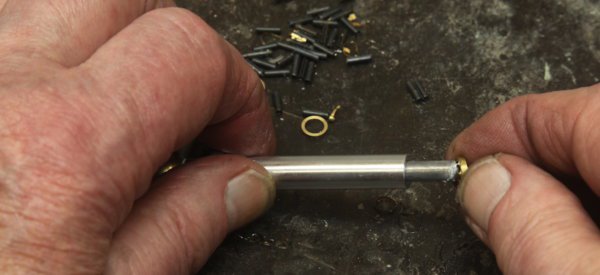
And follow it with a small brass washer, which I make by drilling 1/4" rod (#12 again) and part off in the lathe:
I have a special little drill jig I made from O-1 steel and hardened. It allows me to stick the end of the bearing shaft through the hole and drill a 1/16" hole about .01" from the brass washer. By using this jig, I can accommodate any thickness of washer, or length of bearing, so when I make those parts I don't have any nasty tolerances to hold. I cheat whenever I can:
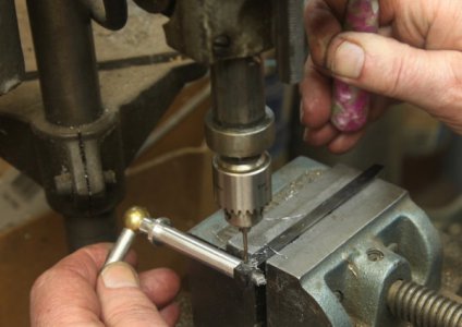
The drill press is one of those tiny Electro-Mechano precision ones that cost about $1500 direct or in my case, two hundred bucks on eBay. A swell little machine, but it does take a little while to get used to the peculiar pulsing mechanical speed control with its centrifugal governor.
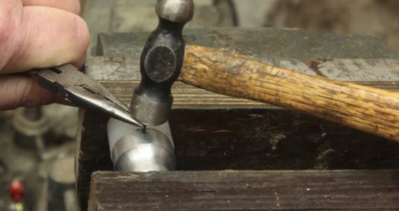
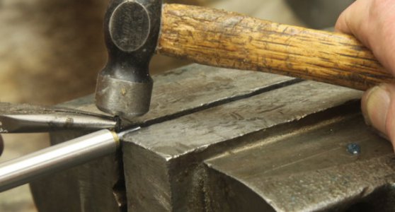
Back to the bench vise to tap in a 1/4" long 1/16" roll pin to retain the assembl;y:
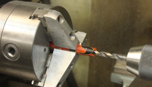
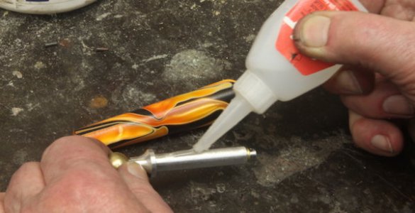
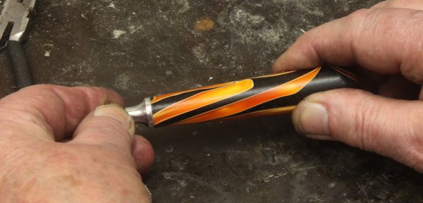
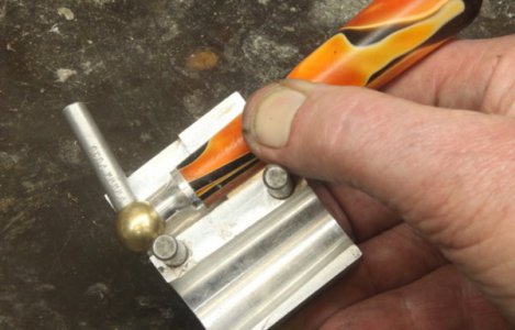
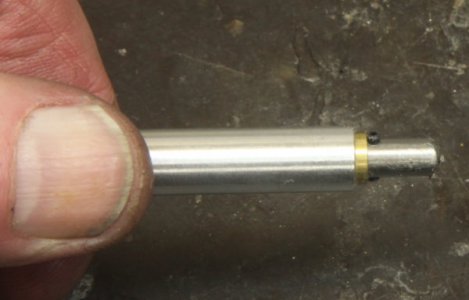
Here's the secret to the handle - I cement it over the bearing, so it looks nice and trim, can't come off, and shows no sign of retaining hardware:
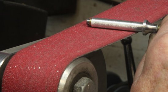
To prepare the bearing for the handle, I run my belt sander super slowly, and ride the bearing on it, holding it at an angle so the coarse grit skids and scuffs a nice pattern on the outside of the bearing:
OK, how about the handle? I make those, too, and I'll post that stuff soon as I have time.

These cranks feature a soft head made of low density polyethylene, an angle of 83-degrees to simulate wrist rotation, and a solid bearing in the handle.
Interestingly, one of the first questions I get about them is, "How do you achieve that angle?" So, I'll start the description with that in mind. . .
The only commercially made part is the little brass ball, which I drill almost all the way through with a 6.4mm drill that gives me a .252: hole, making for a nice sliding fit for a 1/4" precision ground aluminum rod:

Here, I'm using my tiny Rusnok milling machine. I have the ball set into a matching cavity I milled by plunging with sa 1/2" ball end mill into the steel soft jaws on my old 4" Kurt vise. By the way, I get my soft jaws for vises and chucks from monsterjaws.com - no affiliation - they sell CNC made jaws for about what I'd pay for raw material.
A single drop of Loctite 609 green bearing retaining compound goes into the hole:

Then the 1.60" long 1/4" aluminum rod:

A gentle but quick squish in the bench vise forces the green compound right out so I can be assured of complete coverage:

It takes overnight for a complete cure, but it sets up in seconds so it can be handled with no chance of loosening.
Here's another view of Kurt's soft jaws, showing the recess I milled to hold the completed assembly for drilling that 83-degree angle hole:

The little crank arm fits right in there:

A #12 drill gives me about .0015" clearance for a slip fit on my 3/16" diameter steel bearing shaft:

My vise mounted bolt cutter chops off sections of 3/16" steel rod, and they shoot all over the place, so I position a few shallow boxes to catch them so I don't actually have to clean off a section of my bench:

Of course, the bolt cutter leaves nasty deformed cut ends, so it's off to the 2x72 belt grinder for a quick bit of squaring up and chamfering:

The cut end on the left becomes the nice smooth one on the right in almost no time:

Then, it's time for another drip of the green Loctite to secure the bearing shaft:

So, here's that 83-degree elbow, after all:

I milled halfway through one so you could see the inside, where the smaller steel shaft runs right through the ball and the 1/4" crank arm, for a solid joint assembly:

A few years ago I had a steel stamp made so I could mark my stuff, and for this project, I made up a special little fixture that holds it with some inset neodymium magnets while I whack it with my classic B.F.H. to get a good impression, right on center:


As they'd say in a previous century, "None Genuine Without This Brand."
NEXT UP IS THE ALUMINUM BEARING FOR THE HANDLE . . . . . . .
The handle bearing starts out as a 2.25" long piece of 1/2" 6061 aluminum rod, and I drill through it with a number 12 drill bit:

That's not the drill bit I actually use - it's a staged photo. I really use a parabolic drill for better chip clearance, and to try to keep things straight and on center, I drill halfway from each end. The #12 bit gives me just enough clearance for the bearing shaft and lubrication.
One end gets a touch with a 90-degree countersink to butt up against the brass ball:

Flipping it around, I turn down the outside of the shaft to 5/16." Gripping the last half inch in the collet, I can just manage to turn down the 1.75" I need without supporting the outboard end:

Switching to a 5/16" collet and gripping up close, I use a 1/4" radius form tool to shape the end of the bearing:

Here's a shot of the stages in making the bearing:

Painting on a thick layer of white lithium grease, I squidge the bearing onto the shaft:

And follow it with a small brass washer, which I make by drilling 1/4" rod (#12 again) and part off in the lathe:

I have a special little drill jig I made from O-1 steel and hardened. It allows me to stick the end of the bearing shaft through the hole and drill a 1/16" hole about .01" from the brass washer. By using this jig, I can accommodate any thickness of washer, or length of bearing, so when I make those parts I don't have any nasty tolerances to hold. I cheat whenever I can:

The drill press is one of those tiny Electro-Mechano precision ones that cost about $1500 direct or in my case, two hundred bucks on eBay. A swell little machine, but it does take a little while to get used to the peculiar pulsing mechanical speed control with its centrifugal governor.
Back to the bench vise to tap in a 1/4" long 1/16" roll pin to retain the assembl;y:

Here's the secret to the handle - I cement it over the bearing, so it looks nice and trim, can't come off, and shows no sign of retaining hardware:

To prepare the bearing for the handle, I run my belt sander super slowly, and ride the bearing on it, holding it at an angle so the coarse grit skids and scuffs a nice pattern on the outside of the bearing:

OK, how about the handle? I make those, too, and I'll post that stuff soon as I have time.

Last edited:

