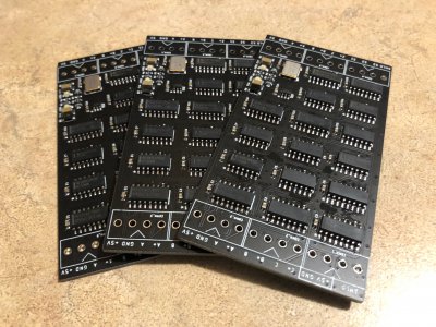
Since we are getting close to some robot action, I think now would be a good time to discuss the mechanics and kinematics which the software will need to handle.
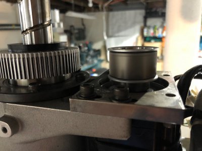
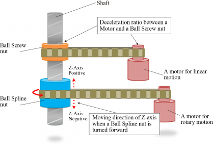
First thing to discuss is the T3/T4 motor assembly. The two motors are belted to the two nuts on the ballscrew/ballspline. The T3 motor drives the upper nut which is a traditional ballscrew nut. There is a 2:1 gear reduction in the belt system. The T4 motor drives the lower nut which is a ballspline (free to slide axially, fixed rotationally). It has a 1:1 belt drive ratio as well as a planetary gearbox with a currently unknown ratio.
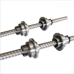
The screw is able to translate and rotate with the differential motion between the two nuts. They follow the equations:
Z = (T3 - T4)*Screw Lead
U = T4
Where Z is the change of position in the vertical cardinal axis, U is rotation about the Z axis, T3 is the rotation of the ballscrew nut, T4 is rotation of the ballspline nut. Screw lead refers to the linear distance traveled per rotation of the ballscrew nut
Since the PLC is controlling the motors and not the end effector directly, we need to rearrange these equations to solve for the motion of T3 and T4. This gives the following solutions:
T3 = (Z/Screw Lead) + U
T4 = U
In the controller, the real motors are Servo Axes and the cardinal axes (X, Y, Z, U) are considered Virtual Axes. Virtual axes can be commanded just like real motors, but are only used for calculations. In the case of the robot, the Virtual Axes Z & U compute the motor axes T3 and T4. Virtual Axes X & Y are used to compute T1 & T2 through the built in kinematics functions. I may also add a Z_Rot virtual axis to handle the screw pitch calculation.
Currently the built in robot kinematics for the SCARA variety do not handle the Z/U interaction, so I will need to handle it in the code manually. To do this, I will need to electronically gear (does exactly as the name implies) Z_Rot to Z with the ratio equivalent to the screw lead. Then T3 will be electronically geared to both Z_Rot and U. T4 will be electronically geared to only U.
The gearing can be set in the startup routine. Once it has been enabled, it is continuously calculated in the background by the PLC motion planner. What this means is I can command motion on Z and U (in inches and degrees respectively) and the PLC will figure out how to move T3 & T4 to make that happen.
The motion planner also has coordinate systems. These allow you to add kinematics to your motors. Kinematics in robotics refers to the calculations required to convert desired motion in an X, Y, and Z Cartesian coordinate system (the one we are familiar with) to motion on the joint motors. These equations become highly non-linear and motion in a straight line in Cartesian space can create some very complicated motion at the motors.
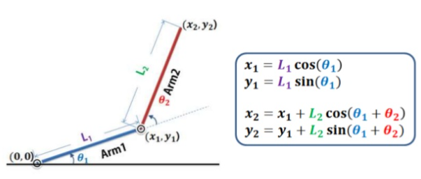
Forward Kinematics are the simpler equation to solve and the SCARA robot is one of the easiest geometries to do it on. With a basic familiarity in trigonometry you should be able to see how knowing the joint angles (theta 1 and theta 2 in this example) allow you to calculate the end effector position (X2, Y2 in this example). The calculations ignore the Z and U axes.
 Inverse Kinematics
 are the devilishly complicated brother to the forward kinematics. With the inverse kinematics your goals is to determine the joint angles needed to give a defined end effector position. This is done using typically using Devanit-Hartenberg parameters and the homogenous transformation. This is usually a graduate level subject. Unfortunately I never got the chance to cover it in school, but I did buy a textbook and spent a year and a half studying the subject. It is still about as clear as mud to me

. Shown below is a picture of the solution to the inverse kinematics for this robot.
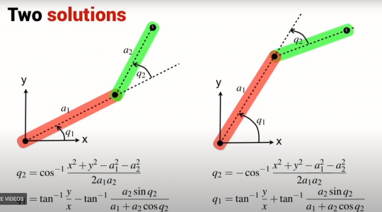
Notice there are two solutions. While going through the math, you end up taking a square root and introduce a plus-or-minus into the equation. This means there are now two equally valid solutions. In real life, this holds true as the robot can approach the desired position from two different angles and get perfectly valid results.
To make it worse, there are many positions within the workspace where one or neither solution is valid. This occurs when the motion required to reach that position is beyond the physical limitations of the mechanics of the robot (for example a position further away than the arm is long, or one near the right edge of the workspace where one of the solutions requires the arm to rotate further than it can go, but the second solution would be valid). The kinematics alone won't always help you find the right solution since they return answers without boundaries or limitations taken into account. The robot control software needs to be able to make decisions on the fly as to which solution is the appropriate one to use (think of cost minimization functions and such). With the PLC kinematics, you must select if you wish to use a right arm or left arm solution when enabling the kinematics. This can be switched at runtime but it creates a discontinuity in the motion control as the arm flips to face the other direction. You can see this happening repeatedly in the second video in post #4 of this thread.
In 6 axis robot arms it gets even worse. With all the extra joints, additional plus-or-minuses get introduced into the solution and you end up with 8 potentially valid solutions for any given position and orientation. UGH!
And after all of that, you have only figured out what the motor positions are to get the robot to a particular position. Let's say you want the end effector to move in a straight line in Cartesian space, you now have to consider path planning. This is done with the derivative of the homogenous transformation called the Jacobian. I never got to learning this by hand. But it allows you to create the non-linear function which the motor must execute to generate linear motion at the end of the arm through some god-awful math that looks like this:
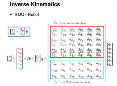
Thankfully, the PLC handles this part for you behind the scenes. All you have to do is command motion in X and Y like a CNC machine, and it will do all the math to make the motors move where they need to.
This is a super deep subject that makes me really excited, but I think I'll stop here before I bore anyone. If you want to hear more, or have questions, let me know and I'll make a follow-up post.
-Mike

