- Joined
- Apr 25, 2024
- Messages
- 53
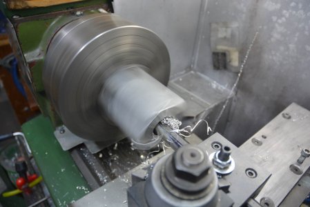
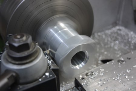
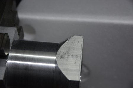
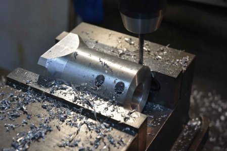
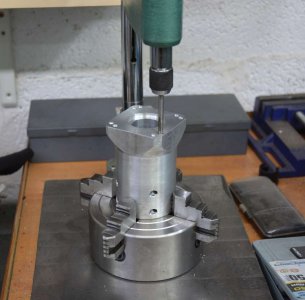
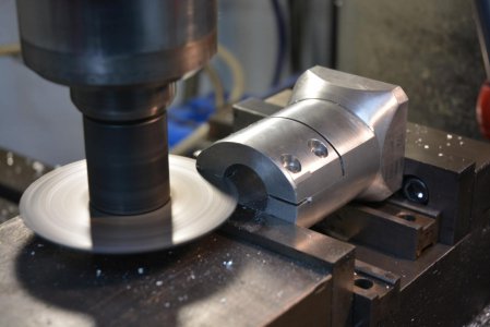
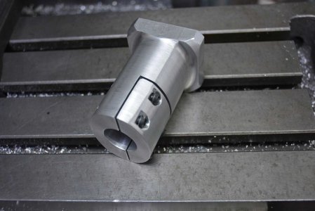
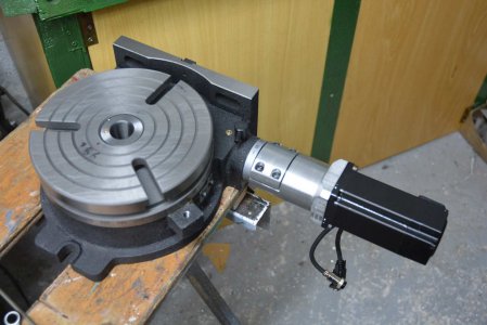
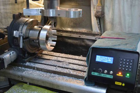
I am a newbie here, only my second post. I hope that this is the best subforum for this. If not maybe an admin can move it. My previous post showed a motorcycle clutch that I made. One of the tools that I used for that was a rotab that I had motorised. There were two aspects to this, firstly some simple turning to make a solid connection between the motor and rotab. Secondly a power supply and control box to enable semi automatic control. I also had in mind that it should be done so that I could quickly switch between the semi-automated but manually demanded control function and CNC driven as a fourth axis.
There are three manually demanded functions that I built into the software, viz;
1. Move to a set angle.
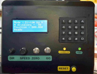
2. Divide a circle into a specified number of equally spaced angles and index around on the press of a button.
3. Continuous jogging whilst holding a button.
The direction and speed of movement are under operator control.
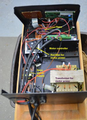
The heart of the control system is an Arduino Nano which accepts instructions from buttons, a keypad and potentiometer on the front panel. The Nano outputs step and direction signals which are fed into an off the shelf stepper driver which in turn drives a Nema24 4Nm closed loop stepper motor.
To change over to working as a CNC 4th axis all that is necessary is to change the input to the driver over to the output of the CNC controller.
Commanded resolution is 0.001 degree. Due to friction it would be unreasonable to expect individual movements that fine but a fine resolution helps with smoothness.
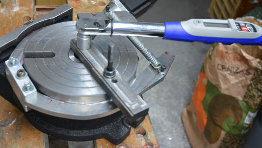
Rather than relying on the worm drive to hold the table against machining forces I have fitted an external drum brake. There is always some backlash in a worm drive and the brake renders that unimportant. The brake is powered by a spring which is released by a pneumatic cylinder when the table needs to move. I include a photo showing the holding torque of the brake being tested.
The brake system is great when the rotab is laying flat but is not so good when upright in the mill, it creates clearance problems. That is the only issued that has shown up in use.


Last edited:

