Quite a while back , I built a steady rest for my lathe. It used the telescoping arms which I really like. I am not happy with the look of the body on the steady rest. I want something closer to the original styling.
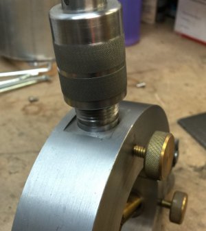
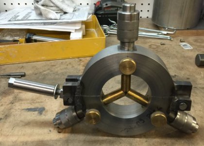
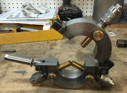
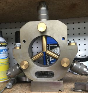 See what I mean. It just don't look right. It functions just fine, it's the look.
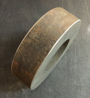
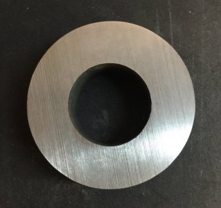 I ordered this piece of steel tubing. It is 6" OD, 3" ID and 1 1/2" thick. I wanted a little bigger OD So I could keep the 4" ID, but it was not available.
I put the tubing in my lathe, faced both sides to 1 1/2" thickness, then turned the ID to 3.140", And the OD TO 5.940" to true it up.
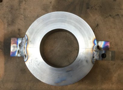
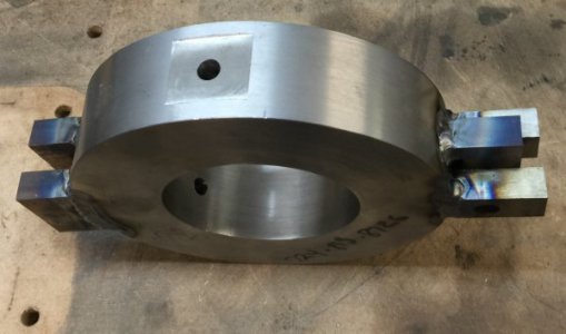
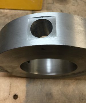
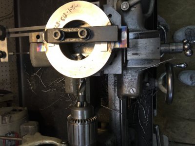
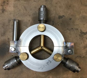
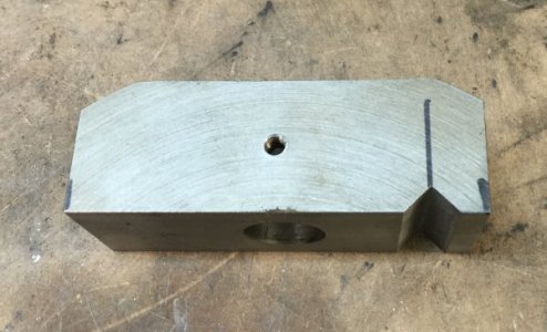
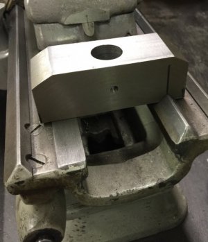
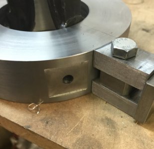 I put the finished ring on my rotary table on the mill , centered it to within .001" , then drilled a .3125 hole every 120 degrees. Next I milled a 1" X 1" flat over each hole. These will get bored to .875" to fit the telescoping assemblies from my old steady rest. You can also see the hinge that is clamped in place and ready to be welded.
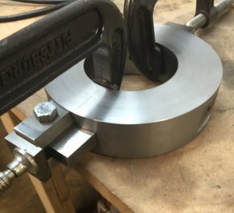 This is another view of the hinge.
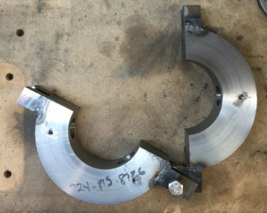
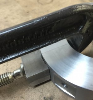 This is the locking bolt block to hold it closed , also clamped in place to be welded. After welding, the ring will be cut in half. The lock bolt will be a swing away bolt.
Now, one other reason for rebuilding the steady rest is the top hole in the old one got drilled at a slight angle instead of square. This makes it not perfectly line up with the bottom two fingers. While it is functional, it is a cosmetic thing and bothered me since I built it. Plus the "look" bothers me.
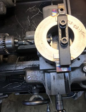
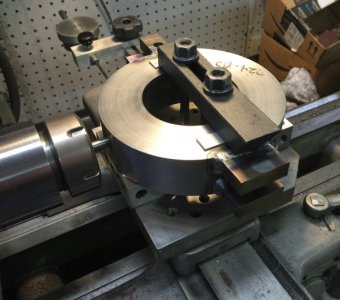
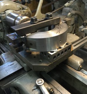
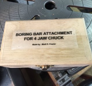
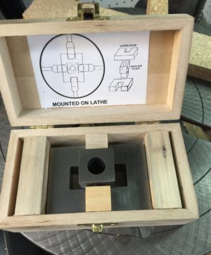
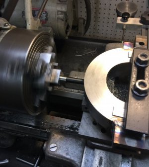
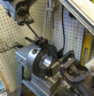
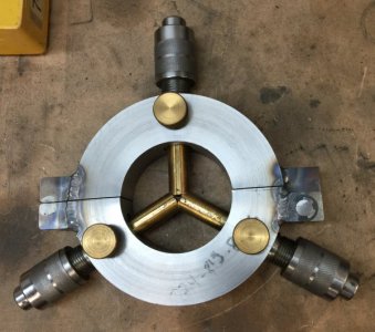
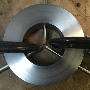 I slid some 5/16" diameter rods in the reamed holes to check the alignment and as you can see here, it is good. The other purpose for these "alignment" rods is, this is too big to put on my mill and I don't own a boring head , however, I will put it on my milling table for my lathe and I can use my 4 jaw chuck boring head conversion to bore the holes on the lathe. ( that is how I did the original one). I will clamp the rod in a collet on the lathe spindle and that will align the hole for boring.
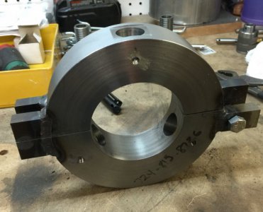
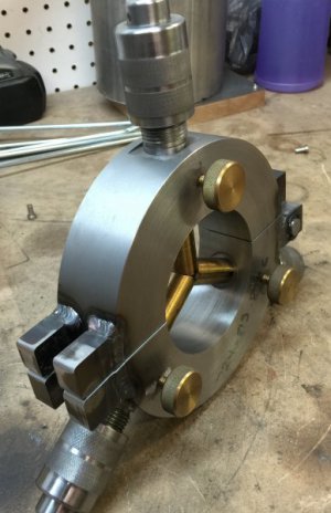
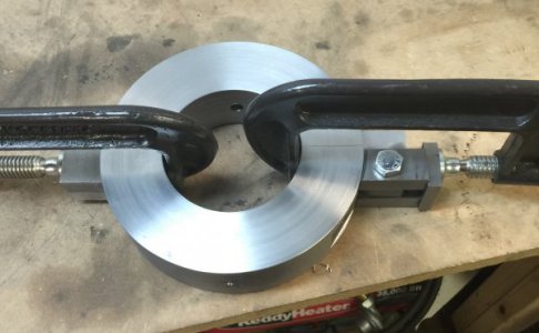 This photo shows the hinge and lock bolt block clamped for welding. I want these TIG welded but I am not allowed any where near a TIG welder. It will screw up my pacemaker. I now am held up until I find someone to weld the assembly.
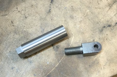
I also have a better idea for the base to mount the steady rest to the lathe.
 See what I mean. It just don't look right. It functions just fine, it's the look.
 I ordered this piece of steel tubing. It is 6" OD, 3" ID and 1 1/2" thick. I wanted a little bigger OD So I could keep the 4" ID, but it was not available.
I put the tubing in my lathe, faced both sides to 1 1/2" thickness, then turned the ID to 3.140", And the OD TO 5.940" to true it up.
 I put the finished ring on my rotary table on the mill , centered it to within .001" , then drilled a .3125 hole every 120 degrees. Next I milled a 1" X 1" flat over each hole. These will get bored to .875" to fit the telescoping assemblies from my old steady rest. You can also see the hinge that is clamped in place and ready to be welded.
 This is another view of the hinge.
 This is the locking bolt block to hold it closed , also clamped in place to be welded. After welding, the ring will be cut in half. The lock bolt will be a swing away bolt.
Now, one other reason for rebuilding the steady rest is the top hole in the old one got drilled at a slight angle instead of square. This makes it not perfectly line up with the bottom two fingers. While it is functional, it is a cosmetic thing and bothered me since I built it. Plus the "look" bothers me.
 I slid some 5/16" diameter rods in the reamed holes to check the alignment and as you can see here, it is good. The other purpose for these "alignment" rods is, this is too big to put on my mill and I don't own a boring head , however, I will put it on my milling table for my lathe and I can use my 4 jaw chuck boring head conversion to bore the holes on the lathe. ( that is how I did the original one). I will clamp the rod in a collet on the lathe spindle and that will align the hole for boring.
 This photo shows the hinge and lock bolt block clamped for welding. I want these TIG welded but I am not allowed any where near a TIG welder. It will screw up my pacemaker. I now am held up until I find someone to weld the assembly.
I also have a better idea for the base to mount the steady rest to the lathe.

