- Joined
- Mar 17, 2018
- Messages
- 1,400
So, my winter bla's set in early this year and haven't done much in the shop. Then right after Christmas my appendix went on me. Because I am a heavy equipment mechanic they wanted me out of work for 6-8 weeks. I felt fine after about 4 days so I made this.
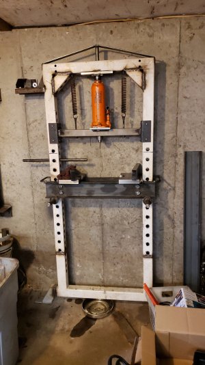
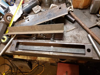
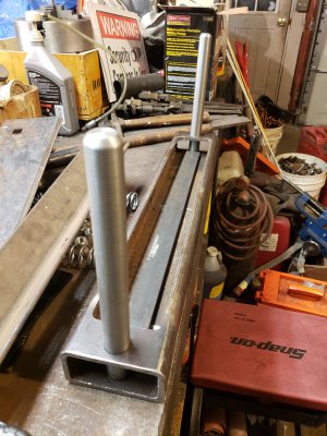
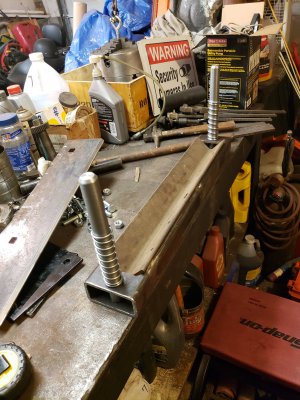
I am very limited on space so it can be used as is, or it can swing out from the wall 90*. Its made out of a commercial weight lifting rack that the cops wanted me to scrap. They are a great source of materials by the way. I have gotten a treadmill with a 3.2hp dc motor, and a bunch of other metal goodies.
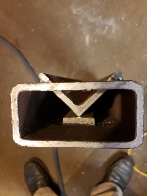
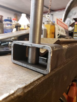
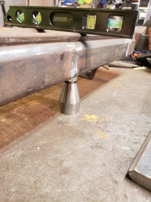
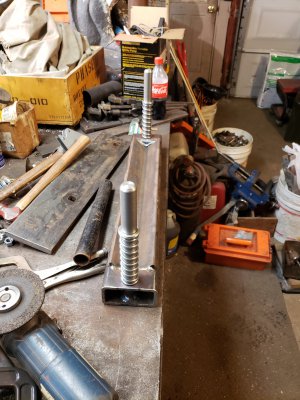
I decided that I needed a press brake so I found a design on line that I based my brake off of. None of the stuff I make comes from a drawing or blueprint, I usually design on the fly. Sometimes it turns into a fail, but I get more done this way.
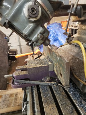
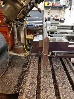
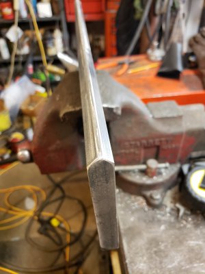
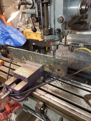
This is a piece of worn out plow blade 5/8" thick. My band saw barely scratched it, so everything had to be done with carbide on the mill. This stuff is wear resistant, brittle, but drills surprisingly easy. As I mentioned elsewhere, don't ever use this for any welding projects. It will fail spectacularly.


