

Hey all, I have seen this question many times on the net, and also on this forum. I have reviewed several from here, including these:
 www.hobby-machinist.com
www.hobby-machinist.com
www.hobby-machinist.com
www.hobby-machinist.com
www.hobby-machinist.com
But I can't seem to apply the information given to my situation. I apologize in advance for asking the same question that I am sure is brought up again and again.
I am refurbishing a 1935 South Bend lathe, though I'm pretty sure the motor is newer than that. Here is it's info tag below. I think it is capacitor start as I see a bump on it's side. The original wall plug is a 220 V plug and wiring seem to have been for high volts.
Left side of tag (right side is cut off, see other image below)

Right side of tag:

I have a Westinghouse Drum switch that looks like this (not cleaned up yet).

I verified that it has It has connections like this:


And with switch in the center, there is no connection. This seems standard to other posts I have seen about this.
When I took the wiring apart during painting etc, I tried to label the wires. But 2 or more of my tags came off unnoticed by me until too late. So I'm stuck.
The wires coming out of the motor were nicely labeled with P1, P2, T2, T3, T4, T5, T8

Below is the other end of wires that were connected to the motor:

It has red, black, yellow and orange #1 and orange #2
The wires coming out of the motor. connections were as follows (see also diagram below):
P1 --> orange #1
P2 --> capped, not used
T2+T3 --> orange #2
T4 --> yellow
T5 --> red
T8 --> black
These wire run to a junction box in the back of the lathe. And here they connect to a different set of wires that run to the drum switch. In the photo below, only these second set of wires are shown:

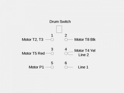
The connections here are as below (see also diagram below)
yellow --> switch pole 3
orange #1 --> switch pole 6
orange #2 --> ?? (tag lost)
red --> switch pole 4
black --> ?? (tag lost)
The secondary wires reach the end of the arm, where the switch is mounted:

There are 6 wires running from the junction box to the end of the switch arm. One of them seemed to be capped off and not used, though I'm not sure.
Here is the best I can diagram my current knowledge of the original setup.

To summarize:
I want Drum switch to switch this 220 V, single phase motor in forward, reverse directions, and of course also off.
Any help will be appreciated!
K. Toppenberg
Problem with wiring of 1946 lathe and drum switch
Hello everyone. I've been searching for a solution to my wiring problem for days and the longer I search the more confused I get. I'm electrically challenged and flunked out of Electrical Engineering 101 in college. I enjoyed building Heathkit projects but that only required soldering skills...
www.hobby-machinist.com
Drum Switch Question
Are drum switches used to turn the power on and off as well as changing direction or does one need a power switch to turn the power on and the drum switch only changes the direction ? Can one get drums for 120v 1ph, 240v 1ph and 240v 3ph or they all the same if rated high enough say like this on...
www.hobby-machinist.com
Drum Switch again
Hello I know this topic has been discussed to death on here as I just read through every thread I could find with the search term "drum switch" ... so I apologize ahead of time if somewhere this particular configuration has been discussed but I was unable to find it. I have a single phase, dual...
www.hobby-machinist.com
But I can't seem to apply the information given to my situation. I apologize in advance for asking the same question that I am sure is brought up again and again.
I am refurbishing a 1935 South Bend lathe, though I'm pretty sure the motor is newer than that. Here is it's info tag below. I think it is capacitor start as I see a bump on it's side. The original wall plug is a 220 V plug and wiring seem to have been for high volts.
Left side of tag (right side is cut off, see other image below)
Right side of tag:
I have a Westinghouse Drum switch that looks like this (not cleaned up yet).
I verified that it has It has connections like this:
And with switch in the center, there is no connection. This seems standard to other posts I have seen about this.
When I took the wiring apart during painting etc, I tried to label the wires. But 2 or more of my tags came off unnoticed by me until too late. So I'm stuck.
The wires coming out of the motor were nicely labeled with P1, P2, T2, T3, T4, T5, T8
Below is the other end of wires that were connected to the motor:
It has red, black, yellow and orange #1 and orange #2
The wires coming out of the motor. connections were as follows (see also diagram below):
P1 --> orange #1
P2 --> capped, not used
T2+T3 --> orange #2
T4 --> yellow
T5 --> red
T8 --> black
These wire run to a junction box in the back of the lathe. And here they connect to a different set of wires that run to the drum switch. In the photo below, only these second set of wires are shown:
The connections here are as below (see also diagram below)
yellow --> switch pole 3
orange #1 --> switch pole 6
orange #2 --> ?? (tag lost)
red --> switch pole 4
black --> ?? (tag lost)
The secondary wires reach the end of the arm, where the switch is mounted:
There are 6 wires running from the junction box to the end of the switch arm. One of them seemed to be capped off and not used, though I'm not sure.
Here is the best I can diagram my current knowledge of the original setup.
To summarize:
I want Drum switch to switch this 220 V, single phase motor in forward, reverse directions, and of course also off.
Any help will be appreciated!
K. Toppenberg
Last edited:


")


