New To Me, Jet 1336pbd - With Some "issues"

Benny,
I appreciate your post. I knew some of that, but no real details. The photo I posted is of one of the bearings that is currently in the lathe. I'm traveling today and only following this on my phone (and tablet when in the hotel), so I haven't looked at the additional info you have provided. Wouldn't the part number marked on the bearing reflect the precision spec of the bearing?


Sent from my iPhone using Tapatalk
 
Last edited:
Now I have glanced through the first few pages of the 258 in the Timken document you linked. The NSK bearing number referenced by Jet, which matches the bearing I photographed, does not attempt to reflect as many details. I'll look at the NSK site to see if I can learn more. Thanks again for the info. If you know an easier way to cross reference the NSK bearing to a superior Timken bearing I would be interested in learning it.


Sent from my iPad using Tapatalk
 
I see that the number marked is a standard part number which can be used to view a similar part in another company's catalog. I'll check this out.


Sent from my iPad using Tapatalk
 
Well, I'm dumber than before (or I am aware of more of my ignorance).
Motion Industries has a web page that lists my bearing along with bearings they call "substitutes", but the max RPM and load data differ among the original and substitutes. For now, I think I'll just stay with the same part/manufacturer's bearings that I find in the headstock (which are probably good enough) instead of trying to second guess myself and the manufacturer. "Best is the enemy of good enough."


Sent from my iPad using Tapatalk
 
Benny,
I appreciate your post. I knew some of that, but no real details. The photo I posted is of one of the bearings that is currently in the lathe. ......................... Wouldn't the part number marked on the bearing reflect the precision spec of the bearing?

Steve,
Sorry, I not sure about the labeling methods used by the different manufacturers to indicate bearing precision. The company that I retired from used a number of “Special” bearings in the machines they manufactured. As I recall Timken used a grading and selection process for the special roller bearings we received. Our engineers specified the bearing cone, cup, rollers and bearing class. Timken selected the best components during the manufacturing cycle, inspected and (banded) them together as a special assembly. That method seems to be indicated as still used in the link provided. We had to order them way in advance of requirements because of their manufacturing procedures and the quantities we used. I also recall that we used a “special” sealed ball bearing by a different manufacturer where only thing special was the lubricating grease required for very high operating speeds in our application. If I recall correctly these bearings once unpackaged and installed had no indication of their special features. This often resulted in problems when customer maintenance personnel purchased replacements from their local suppliers because they were cheaper. They did not always get the accuracy or bearing life because they had lost the “special features” of the bearings.

In my collection of "hobby hoarded stuff", I have a New Departure branded machine tool bearing with the box labeled “Gold Series”. I have not needed it or opened the box to see if the bearing itself is marked. Maybe I will if I can find it.

Motion Industries has a web page that lists my bearing along with bearings they call "substitutes", but the max RPM and load data differ among the original and substitutes. For now, I think I'll just stay with the same part/manufacturer's bearings that I find in the headstock (which are probably good enough) instead of trying to second guess myself and the manufacturer. "Best is the enemy of good enough."

Steve,
I am sure that you are right that the off-the-shelf bearings will probably be okay if they provide the accuracy “wanted” by us hobbyist. I have been researching for related inspection information because the machine I need to get operational has seen some abuse. I have seen a little information about spindle TIR but not a lot. Most of the manuals I have looked at for the import machines are lacking in definitive information or full of errors.

Benny
The Orphanage Never Closes
 
It looks to me like the NSK bearings and the substitutes all use numbers that are considered an ISO numbering standard. So a bearing marked 30211 from Timken, NSK, etc, all have the same bore, OD, and width. However, there are different prefixes used be the manufacturers that signify additional specs, such as the HR prefix and J suffix that appears on my bearing. J means it's capable of withstanding a higher dynamic load I believe. A suffix of C is not capable of handling high RPMs (so We wouldn't use that).
I am interested in learning what runout to expect from the bearings mentioned by Jet. I believe my original manual actually has a list of brand name and part number for the bearings used in my lathe. Once I get home I'll dig it out and post the info. Thank you again; I find this to be a fascinating subject in an area that I never dealt with in my career as an engineer.


Sent from my iPhone using Tapatalk
 
Today I removed the headstock from the lathe. It was easy, four screws and big grunt to lift it. I didn't completely remove it; I just moved it aside while I removed the shank of the cap screw that a previous owner had broken. I know I'll have to readjust it, but I would have wanted to remove it anyway to clean it all up.

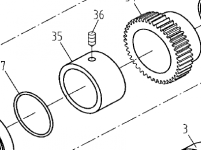
Also, I tried to get the spindle to budge. I tried tapping it with a dead-blow hammer, like a couple of people on YouTube, but no luck. I didn't think I should pound it too hard, so, I'll get a large piece of all-thread and try to gently, but firmly, persuade it like I discussed earlier. While I was studying the spindle, I was once again bothered by the fact that the pulleys and gear on the spindle (except for the bullgear) all slide along the spindle, roughly 3/8 or more inches. They have to be able to spin freely when the lathe is in backgear, but they should not slide axially on the spindle. The axial play is enough to allow the pulley next to the bullgear to disengage from the bullgear when the locking pin should keep them turning together. I don't see any way to prevent the axial movement the way my spindle is now. There is a spacer with a set screw at the left end of the spindle, just inside the left bearing. It's about 3/8 or so wide. Looking at it I wondered if there should be another spacer to take up the additional play. Then I looked at the diagram for the BDB-1340 again. The spacer in that diagram (which appears as part #35 here) looks like it would be much wider than the spacer on mine:
upload_2016-1-29_21-29-52.png

Could one of you with a BDB-1340, or better yet with a 13xxPBD measure, or even estimate, the axial length of that spacer? If it's nearly 5/8 or 3/4 inch (or 18 mm) or longer, then my mystery is solved and I will know that the spacer on mine is simply the wrong spacer.
Thanks!
Steve
 
Today I removed the headstock from the lathe. It was easy, four screws and big grunt to lift it. I didn't completely remove it; I just moved it aside while I removed the shank of the cap screw that a previous owner had broken. I know I'll have to readjust it, but I would have wanted to remove it anyway to clean it all up.

Also, I tried to get the spindle to budge. I tried tapping it with a dead-blow hammer, like a couple of people on YouTube, but no luck. I didn't think I should pound it too hard, so, I'll get a large piece of all-thread and try to gently, but firmly, persuade it like I discussed earlier. While I was studying the spindle, I was once again bothered by the fact that the pulleys and gear on the spindle (except for the bullgear) all slide along the spindle, roughly 3/8 or more inches. They have to be able to spin freely when the lathe is in backgear, but they should not slide axially on the spindle. The axial play is enough to allow the pulley next to the bullgear to disengage from the bullgear when the locking pin should keep them turning together. I don't see any way to prevent the axial movement the way my spindle is now. There is a spacer with a set screw at the left end of the spindle, just inside the left bearing. It's about 3/8 or so wide. Looking at it I wondered if there should be another spacer to take up the additional play. Then I looked at the diagram for the BDB-1340 again. The spacer in that diagram (which appears as part #35 here) looks like it would be much wider than the spacer on mine.

Could one of you with a BDB-1340, or better yet with a 13xxPBD measure, or even estimate, the axial length of that spacer? If it's nearly 5/8 or 3/4 inch (or 18 mm) or longer, then my mystery is solved and I will know that the spacer on mine is simply the wrong spacer.
Thanks!
Steve
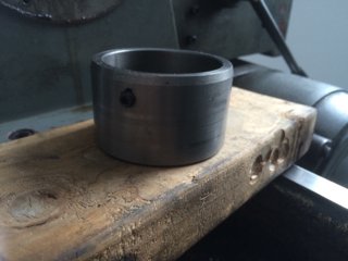
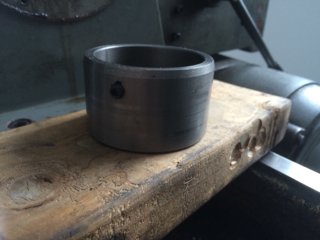
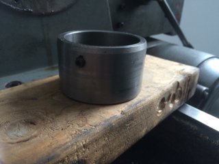
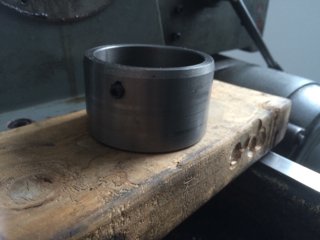
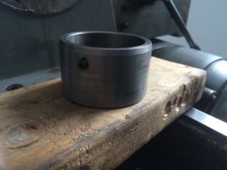
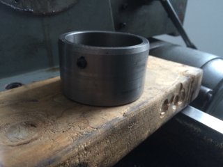
I was wrong. It was tucked in under the rubber oil seal of the outboard bearing. I'll have to figure that out. I don't think that it should have been. It really is wider than I expected.
1d8773f6f0e676b6d876ab8a2552c2b3.jpg


Sent from my iPhone using Tapatalk

1d8773f6f0e676b6d876ab8a2552c2b3.jpg

1d8773f6f0e676b6d876ab8a2552c2b3.jpg

1d8773f6f0e676b6d876ab8a2552c2b3.jpg

1d8773f6f0e676b6d876ab8a2552c2b3.jpg

1d8773f6f0e676b6d876ab8a2552c2b3.jpg
 
hmmmm........a mystery, but I am following along.......
-brino
 
Last edited:
Yes it goes into the seal. It is actually a bad design as it can allow lube oil to leak out, all be it slowly as the oil level at rest is below that level. Still makes a mess though.
Pierre
 
Back
Top