- Joined
- Feb 5, 2015
- Messages
- 662
I have the impression that most hobbyists have fairly small lathes. Many small imported lathes don't have back gears and, if the machines are not of gear-head construction, sometimes there is a need for slower speed/higher torque. My smaller lathe is an example and this short post describes a tool I made to alleviate the problem.
This Emco lathe is satisfactory for most of the small parts that I make; the machine has a tapered roller bearing high speed spindle that is helpful for turning small diameter, non-ferrous materials. I don't miss the lack of a quick-change gear box because the small threads I mostly require are always chased rather than single-pointed. This is a quicker and more accurate means of threading for my needs - a single, slow pass and the job is done - no part deflection from single-pointing and frequently more accurate since dies are available in 3A tolerances down to #0-80.
BUT occasionally the need arises for more grunt or lower speeds, requiring a back gear which this small Austrian lathe does NOT have. If I need to run a forming tool, drill a large hole, part off a large diameter steel workpiece, run a big hole-saw or even die-thread a large diameter, the machine can't provide adequate torque because the drive belt slips.
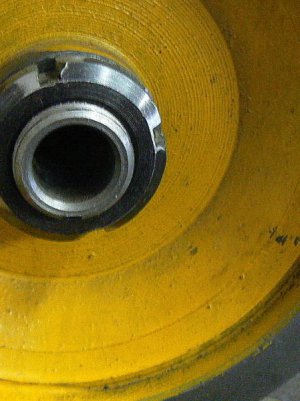
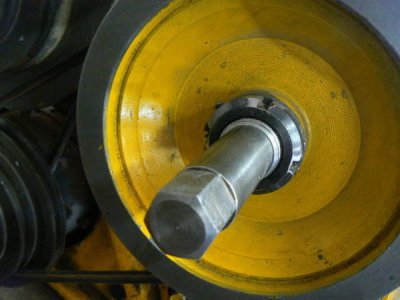
Rotating the spindle by hand was the obvious solution and this was what I did for many years … until I spent an entire day threading some 5/8 - 11 steel studs for my brother-in-law. My left hand was sore for days from rotating the chuck. I decided to make an adaptor for the rear of the spindle to make hand-rotation easier. Not an easy task, however, because of the spindle configuration:
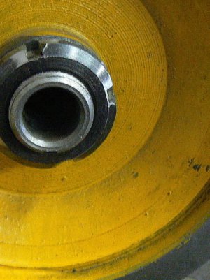
There are only a few threads exposed on the back of the spindle and not enough room to attach an extension, especially one that must transmit torque in either direction - the only option I could see was to grip the spindle bore (or else install a handle on the pulley like mini-lathe owners sometimes do. I had a couple of objections to that method.
I also thought about making an expanding mandrel but recalling how difficult it was to manually rotate the spindle for large thread chasing, I couldn't visualize the mandrel gripping tightly enough on the relatively small (~7/8) bore diameter - I was certain it would slip. (At least, that was my thinking at the time, as I considered my sore hand.)
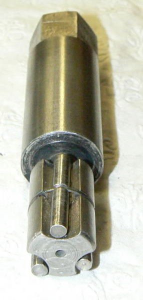
What I needed was a means to grip the bore that would tighten as the torque requirement increased. After thinking about this off-and-on for a few days, I decided that a wedge mechanism could do the job if I implemented it properly. Here's what I came up with:
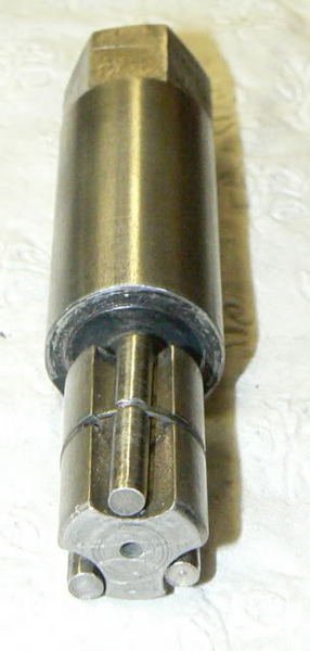
The part is made from 1-1/4 diameter oil-hardening drill rod; hexagonal flats are milled on one end for a socket wrench. The near end of the body is turned .005 inches under the spindle bore. Three shallow circular grooves are equally spaced about the smaller diameter. In these grooves ride three pins (diameters need to be experimentally determined as described later).
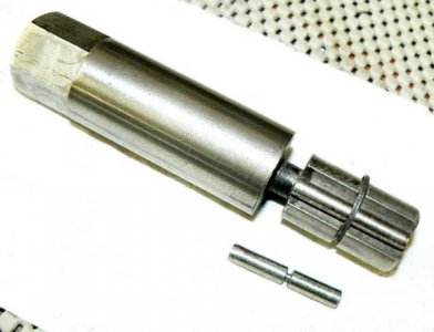
Here is another view of the tool with one of the pins removed:
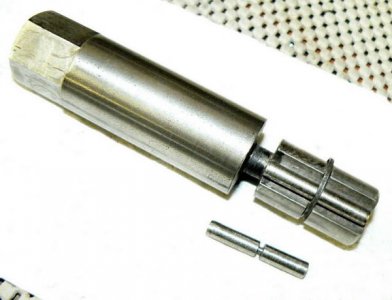
The three pins are also made from drill rod and torch-hardened. The small groove turned into the pins is so the pins can be secured to the main body of the tool with a retaining ring. The main tool body is also grooved for the retaining ring as can be seen. The retaining ring was made by turning, boring and parting off a thin piece of the drill rod then slicing through an edge. The dimensions of the ring aren't critical: outside diameter needs to be .005 - .010 smaller than the spindle bore and the inside diameter slected to loosely secure the pins when they are "at rest" in the tool body. There must be enough clearance for the roller pins to freely rotate when inserted into the spndle.
A jeweler's saw was used to cut through the retaining ring on one side so that it resembled a "flattened" split lockwasher. After all the parts were made, they were individually torch-heated to bright orange then oil-quenched. After light-sanding to remove burnt oil and oxides, the parts were drawn back to a straw color (in a toaster oven). Some sanding and some steel wool touched up the parts before they were assembled although no particular care was taken to make the tool "pretty", as you can see. The retainer can be expanded slightly and the pins slipped under it, one by one, until they are secured by the ring to the tool body.
At this point, most will have already intuited how the tool functions. The end of the tool slips into the spindle bore (the three rollers, when riding at the bottom of the shallow circular grooves slide easily into the bore with about .002 inches clearance). When the tool is rotated - in either direction - the three pins roll in the shallow circular grooves (ramps) in the body. The pins roll up the ramps until they come into contact with the spindle bore.
The pins can't roll any further so they wedge into tight contact with the spindle bore - as more torque is applied to the body of the tool, the tighter the interference between tool body, roller pins and spindle bore. I had to make three sets of roller pins before I got the clearance just right - too little clearance and the tool will not easily insert into the bore (and this is not an area where one wants to tap something into place). If the clearance is too great, the roller pins will slip. I didn’t find it possible to determine the diameters beforehand so I just experimented -
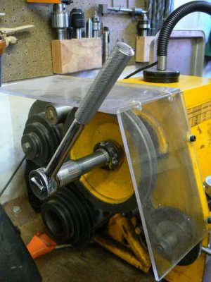
Here's a photo of the spindle wrench slipped into the spindle bore:
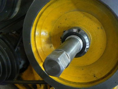
To use the wrench, one of the drive belts is removed from either the motor or the countershaft, so that the spindle rotates freely and so that bad things don't happen if the lathe is accidentally powered up. A 1/2 inch drive ratchet is used to rotate the spindle. Even if the belts are not removed and the lathe is powered up, the wrench will just ratchet UNLESS the lathe is powered in reverse. Best to remove the belt.
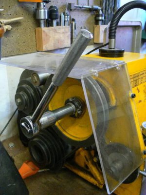
The tool has been useful in overcoming certain limitations of my small lathe. The spindle bore should be clean and relatively free of coolant to be completely effective.
This Emco lathe is satisfactory for most of the small parts that I make; the machine has a tapered roller bearing high speed spindle that is helpful for turning small diameter, non-ferrous materials. I don't miss the lack of a quick-change gear box because the small threads I mostly require are always chased rather than single-pointed. This is a quicker and more accurate means of threading for my needs - a single, slow pass and the job is done - no part deflection from single-pointing and frequently more accurate since dies are available in 3A tolerances down to #0-80.
BUT occasionally the need arises for more grunt or lower speeds, requiring a back gear which this small Austrian lathe does NOT have. If I need to run a forming tool, drill a large hole, part off a large diameter steel workpiece, run a big hole-saw or even die-thread a large diameter, the machine can't provide adequate torque because the drive belt slips.
Rotating the spindle by hand was the obvious solution and this was what I did for many years … until I spent an entire day threading some 5/8 - 11 steel studs for my brother-in-law. My left hand was sore for days from rotating the chuck. I decided to make an adaptor for the rear of the spindle to make hand-rotation easier. Not an easy task, however, because of the spindle configuration:

There are only a few threads exposed on the back of the spindle and not enough room to attach an extension, especially one that must transmit torque in either direction - the only option I could see was to grip the spindle bore (or else install a handle on the pulley like mini-lathe owners sometimes do. I had a couple of objections to that method.
I also thought about making an expanding mandrel but recalling how difficult it was to manually rotate the spindle for large thread chasing, I couldn't visualize the mandrel gripping tightly enough on the relatively small (~7/8) bore diameter - I was certain it would slip. (At least, that was my thinking at the time, as I considered my sore hand.)
What I needed was a means to grip the bore that would tighten as the torque requirement increased. After thinking about this off-and-on for a few days, I decided that a wedge mechanism could do the job if I implemented it properly. Here's what I came up with:

The part is made from 1-1/4 diameter oil-hardening drill rod; hexagonal flats are milled on one end for a socket wrench. The near end of the body is turned .005 inches under the spindle bore. Three shallow circular grooves are equally spaced about the smaller diameter. In these grooves ride three pins (diameters need to be experimentally determined as described later).
Here is another view of the tool with one of the pins removed:

The three pins are also made from drill rod and torch-hardened. The small groove turned into the pins is so the pins can be secured to the main body of the tool with a retaining ring. The main tool body is also grooved for the retaining ring as can be seen. The retaining ring was made by turning, boring and parting off a thin piece of the drill rod then slicing through an edge. The dimensions of the ring aren't critical: outside diameter needs to be .005 - .010 smaller than the spindle bore and the inside diameter slected to loosely secure the pins when they are "at rest" in the tool body. There must be enough clearance for the roller pins to freely rotate when inserted into the spndle.
A jeweler's saw was used to cut through the retaining ring on one side so that it resembled a "flattened" split lockwasher. After all the parts were made, they were individually torch-heated to bright orange then oil-quenched. After light-sanding to remove burnt oil and oxides, the parts were drawn back to a straw color (in a toaster oven). Some sanding and some steel wool touched up the parts before they were assembled although no particular care was taken to make the tool "pretty", as you can see. The retainer can be expanded slightly and the pins slipped under it, one by one, until they are secured by the ring to the tool body.
At this point, most will have already intuited how the tool functions. The end of the tool slips into the spindle bore (the three rollers, when riding at the bottom of the shallow circular grooves slide easily into the bore with about .002 inches clearance). When the tool is rotated - in either direction - the three pins roll in the shallow circular grooves (ramps) in the body. The pins roll up the ramps until they come into contact with the spindle bore.
The pins can't roll any further so they wedge into tight contact with the spindle bore - as more torque is applied to the body of the tool, the tighter the interference between tool body, roller pins and spindle bore. I had to make three sets of roller pins before I got the clearance just right - too little clearance and the tool will not easily insert into the bore (and this is not an area where one wants to tap something into place). If the clearance is too great, the roller pins will slip. I didn’t find it possible to determine the diameters beforehand so I just experimented -
Here's a photo of the spindle wrench slipped into the spindle bore:

To use the wrench, one of the drive belts is removed from either the motor or the countershaft, so that the spindle rotates freely and so that bad things don't happen if the lathe is accidentally powered up. A 1/2 inch drive ratchet is used to rotate the spindle. Even if the belts are not removed and the lathe is powered up, the wrench will just ratchet UNLESS the lathe is powered in reverse. Best to remove the belt.

The tool has been useful in overcoming certain limitations of my small lathe. The spindle bore should be clean and relatively free of coolant to be completely effective.


