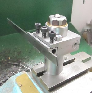
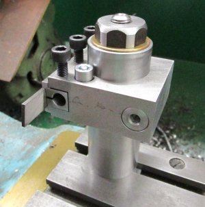
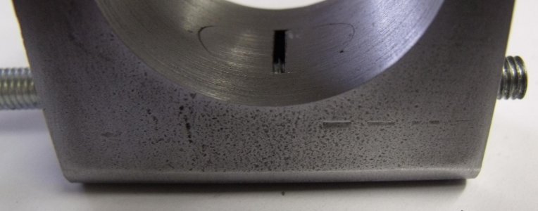
I have been using my Norman style QCTP and have sorted out the problems that came up through use. Instead of placing my findings at the end of the very long thread on making it I thought that it would be better to put everything in one place.
First off you have to measure the distance from the top of the compound to center line on your lathe. 1 3/16" on my craftsman 12x36 lathe.
Next you have to decide on the maximum size tool bits that you will be using. In my case I wanted to be able to use the craftsman tool holders that came with my lathe. Primarily the threading, parting and knurling tool holders. They are .75" tall. Using these made things a little tight and I would not do it again. Future tool holders will be made to fit 3/8 tool bits
Next up is the OD of the post. A larger OD should give more rigidity but if too large creates other problems. A happy medium is needed. I had a round bar slightly larger than 1.25" OD on hand. I turned this down to 1.25 OD. The OD of the post is not critical and can be any convenient size with one exception. The OD has to be larger than the size of the nut so the tool holders can slip over the nut and unto the post.
With center line height, tool bit size and post OD you can determine the dimensions of the base, the tool holders and the height of the post. Here is a sketch of all of the parts. The very bottom is the compound for illustration.
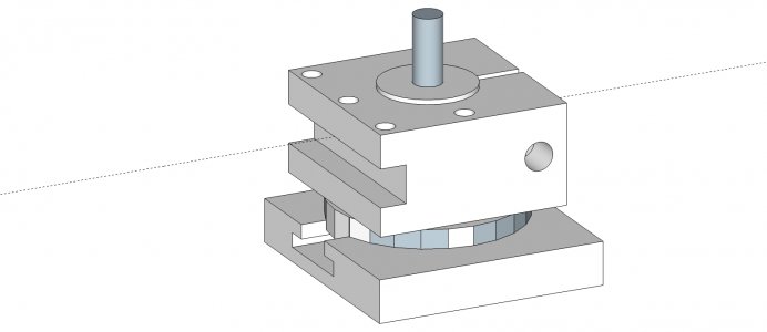
The T nut is first to make. It has to fit in the T slot on the compound. For strength and rigidity you want the leg of the T nut as large as will fit in the slot. In my case that was 5/8."
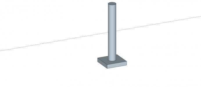
Next up is the base and post. Optimum is to turn this out of one piece of round stock. You want everything square. You can make the base and post separate. I did this because I wanted to use materials on hand. If making the base and post separate you will need to weld the two pieces together. Why? Because the post will slip on the base no matter how tight you tighten the nut on the T nut. The base also has to have a protrusion that precisely fits in the compound slot. Why? Because the base will slip on the compound no matter how tight you tighten the nut on the T nut. If you want to make the tool post indexable you can machine indents in the base. These indents have to precisely line up with the height adjusting screw in the tool holder. Every tool holder that you make will have to have the adjustment screw in the exact same spot. I didn't do this.
The height of the base has to be coordinated with the center line height and the placement of the slot in the tool holder. You have to allow room for height adjustment. On my lathe I had 1 3/16" to work with from the top of the compound the center line. My base is 3/16 high. It was what I had on hand. Even with that I barely had enough room to have some adjustment to bring my craftsman threading tool and parting tool to center line. No problems with any of my other tool bits.
The post has to be taller than the height of the tool holder when the tool bit is at center line. I made my post way longer than it need to be and cut off the extra length. I use this extra piece to test the center holes on the tool holders for fit to the post.
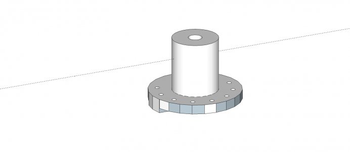
Next are the tool holders. Lots to think about with the tool holders. I made my first batch of tool holders out of 1 1/4 x 2 1/4 1018 bar cut to 2 1/2" length. The ones I am working on now are from 1 1/4 x 2 1018 bar.
I centered the center hole lengthwise and widthwise. You do not have to do this. Some of the tool holders that I currently have on the drawing board are not centered in either direction. The ID of the center hole can only be a couple of thousands larger than the OD of the post. You want a very good fit. The closer the fit the easier it will be to tighten the tool holder to the post. It takes 1/4 turn of the tightening bolt to lock the tool holder to the post on mine. As for the tightening bolt it needs to be at least 5/16 and preferably a grade 8 bolt if going with a 5/16 bolt. I tried a 1/4 bolt and twisted the head off trying to lock the holder to the post. No need to go bigger than a 3/8 bolt.
I used 1/4 bolts for the height adjustment screw. You could use a 10x32 machine screw. The height adjustment screw does not carry any load. Its only function is to raise or lower the holder to get the tool bit on center line. One thing to watch out for is the distance of the height adjustment screw to the post. You need clearance for a wrench or socket to adjust the height. You also need a nut on the height adjustment screw to lock it in place once the tool bit is brought up to center line. I found that the height adjustment screw invariably moved during machining and would even move with normal handling in my tool box. If you don't lock the adjustment screw in place you have to check for center line height every time you use the holder.
For the tool bit slot you want the height of the slot to be slightly taller than the tool bit. No need for a precise fit. And you want the depth of the slot to be slightly shallower than the width of the tool bit. Just enough so that the side of the tool bit is outside of the holder. I didn't do this. If I need to square the tool bit to the chuck I have to place another tool bit between the two. If the tool bit was just slightly proud of the holder I would not have to do this. The placement of the slot has to be coordinated with the height of the base and the center line height with room for adjustment. My base is 3/16" high. My tallest tool was the threading tool at 3/4" or 12/16. I made the bottom of the slot 3/16 up from the bottom of the holder. This gives me just 1/16 of adjustment to bring this tool to center line. All of my other tool bits are not this tall. I have plenty of room to bring my other tool bits up to center line.
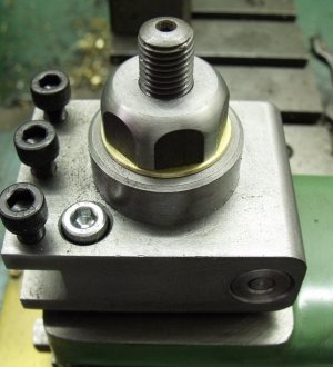
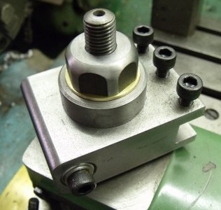
I cut the slot from the center hole to the back of the tool holder with a hacksaw. I was concerned that this slot might not be wide enough to tighten the holder to the post. So far this has not been a problem. I did clean up the slot a little with one of my jewelers files. Below is an example of a tool holder for a 3/8 tool bit
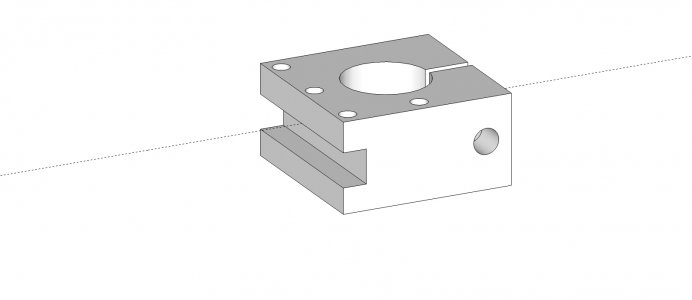
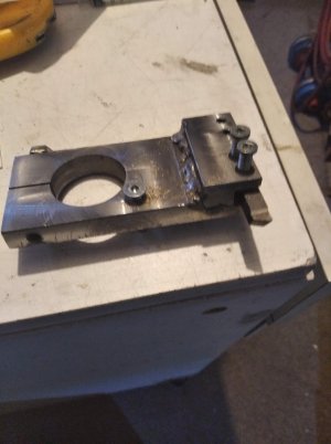
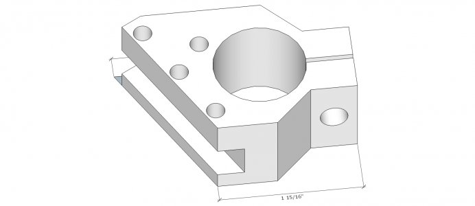
A couple of times I have ran into clearance issues with my original rectangular holders. I am currently in process making this holder which holds the tool bit at a 30 degree angle.
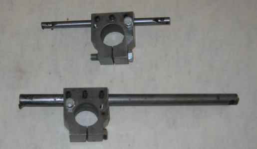
I don't care for my boring bar holders. They seem to work just fine. I have not had a problem using them. What I don't like is holding the bar in place with set screws. The set screws create burs in the bar which makes the bar hard to remove and hard to adjust. I am going to make new holders that clamp the bar in place. I don't have a drawing of this holder. Here is a picture of my current boring bar holders. You can see some of the marks from the set screws on the bottom boring bar just to the left of the tool holder. I would not make them like this again.
There are all kinds of variations that you can make on these Norman style QCTP. I only tried to cover the important basics that you need know to make one. So far I have less than $100 in cost. The major portion of that cost was the 1 1/4 x 2 1/4 1018 bar. The shipping was more than the cost of the steel. I made 7 tool holders out of that bar.
First off you have to measure the distance from the top of the compound to center line on your lathe. 1 3/16" on my craftsman 12x36 lathe.
Next you have to decide on the maximum size tool bits that you will be using. In my case I wanted to be able to use the craftsman tool holders that came with my lathe. Primarily the threading, parting and knurling tool holders. They are .75" tall. Using these made things a little tight and I would not do it again. Future tool holders will be made to fit 3/8 tool bits
Next up is the OD of the post. A larger OD should give more rigidity but if too large creates other problems. A happy medium is needed. I had a round bar slightly larger than 1.25" OD on hand. I turned this down to 1.25 OD. The OD of the post is not critical and can be any convenient size with one exception. The OD has to be larger than the size of the nut so the tool holders can slip over the nut and unto the post.
With center line height, tool bit size and post OD you can determine the dimensions of the base, the tool holders and the height of the post. Here is a sketch of all of the parts. The very bottom is the compound for illustration.

The T nut is first to make. It has to fit in the T slot on the compound. For strength and rigidity you want the leg of the T nut as large as will fit in the slot. In my case that was 5/8."

Next up is the base and post. Optimum is to turn this out of one piece of round stock. You want everything square. You can make the base and post separate. I did this because I wanted to use materials on hand. If making the base and post separate you will need to weld the two pieces together. Why? Because the post will slip on the base no matter how tight you tighten the nut on the T nut. The base also has to have a protrusion that precisely fits in the compound slot. Why? Because the base will slip on the compound no matter how tight you tighten the nut on the T nut. If you want to make the tool post indexable you can machine indents in the base. These indents have to precisely line up with the height adjusting screw in the tool holder. Every tool holder that you make will have to have the adjustment screw in the exact same spot. I didn't do this.
The height of the base has to be coordinated with the center line height and the placement of the slot in the tool holder. You have to allow room for height adjustment. On my lathe I had 1 3/16" to work with from the top of the compound the center line. My base is 3/16 high. It was what I had on hand. Even with that I barely had enough room to have some adjustment to bring my craftsman threading tool and parting tool to center line. No problems with any of my other tool bits.
The post has to be taller than the height of the tool holder when the tool bit is at center line. I made my post way longer than it need to be and cut off the extra length. I use this extra piece to test the center holes on the tool holders for fit to the post.

Next are the tool holders. Lots to think about with the tool holders. I made my first batch of tool holders out of 1 1/4 x 2 1/4 1018 bar cut to 2 1/2" length. The ones I am working on now are from 1 1/4 x 2 1018 bar.
I centered the center hole lengthwise and widthwise. You do not have to do this. Some of the tool holders that I currently have on the drawing board are not centered in either direction. The ID of the center hole can only be a couple of thousands larger than the OD of the post. You want a very good fit. The closer the fit the easier it will be to tighten the tool holder to the post. It takes 1/4 turn of the tightening bolt to lock the tool holder to the post on mine. As for the tightening bolt it needs to be at least 5/16 and preferably a grade 8 bolt if going with a 5/16 bolt. I tried a 1/4 bolt and twisted the head off trying to lock the holder to the post. No need to go bigger than a 3/8 bolt.
I used 1/4 bolts for the height adjustment screw. You could use a 10x32 machine screw. The height adjustment screw does not carry any load. Its only function is to raise or lower the holder to get the tool bit on center line. One thing to watch out for is the distance of the height adjustment screw to the post. You need clearance for a wrench or socket to adjust the height. You also need a nut on the height adjustment screw to lock it in place once the tool bit is brought up to center line. I found that the height adjustment screw invariably moved during machining and would even move with normal handling in my tool box. If you don't lock the adjustment screw in place you have to check for center line height every time you use the holder.
For the tool bit slot you want the height of the slot to be slightly taller than the tool bit. No need for a precise fit. And you want the depth of the slot to be slightly shallower than the width of the tool bit. Just enough so that the side of the tool bit is outside of the holder. I didn't do this. If I need to square the tool bit to the chuck I have to place another tool bit between the two. If the tool bit was just slightly proud of the holder I would not have to do this. The placement of the slot has to be coordinated with the height of the base and the center line height with room for adjustment. My base is 3/16" high. My tallest tool was the threading tool at 3/4" or 12/16. I made the bottom of the slot 3/16 up from the bottom of the holder. This gives me just 1/16 of adjustment to bring this tool to center line. All of my other tool bits are not this tall. I have plenty of room to bring my other tool bits up to center line.
I cut the slot from the center hole to the back of the tool holder with a hacksaw. I was concerned that this slot might not be wide enough to tighten the holder to the post. So far this has not been a problem. I did clean up the slot a little with one of my jewelers files. Below is an example of a tool holder for a 3/8 tool bit

A couple of times I have ran into clearance issues with my original rectangular holders. I am currently in process making this holder which holds the tool bit at a 30 degree angle.

I don't care for my boring bar holders. They seem to work just fine. I have not had a problem using them. What I don't like is holding the bar in place with set screws. The set screws create burs in the bar which makes the bar hard to remove and hard to adjust. I am going to make new holders that clamp the bar in place. I don't have a drawing of this holder. Here is a picture of my current boring bar holders. You can see some of the marks from the set screws on the bottom boring bar just to the left of the tool holder. I would not make them like this again.

There are all kinds of variations that you can make on these Norman style QCTP. I only tried to cover the important basics that you need know to make one. So far I have less than $100 in cost. The major portion of that cost was the 1 1/4 x 2 1/4 1018 bar. The shipping was more than the cost of the steel. I made 7 tool holders out of that bar.
Last edited:

